Basic Civil & Mechanical Engineering: UNIT IV: f. Pumps
Reciprocating Pumps - Classification According to the contact of liquid with one side or both sides of the piston
If a reciprocating pump uses one side of the piston for pumping liquid, then it is known as a Single Acting Reciprocating Pump.
Classification According
To THE CONTACT OF LIQUID WITH ONE SIDE OR BOTH SIDES OF THE PISTON
1. SINGLE ACTING RECIPROCATING PUMP
If
a reciprocating pump uses one side of the piston for pumping liquid, then it is
known as a Single Acting Reciprocating Pump.
Description
(Fig. 1)
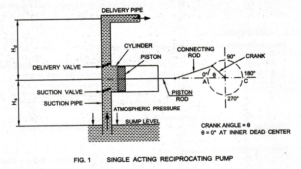
The
main parts of a single acting reciprocating pump are discussed below:
1. Cylinder, Piston, Piston Rod, Connecting
Rod and Crank: A single acting reciprocating pump
consists of a piston (or plunger), which moves forwards and backwards inside a
close fitting cylinder. The movement of the piston is obtained by connecting the piston rod to thecrank by
means of a connecting rod. The crank is rotated by an electric motor.
2. Suction Pipe and Suction Valve:
Suction pipe is connected to the cylinder. Suction valve is one way valve,
i.e., a non-return valve. It allows the liquid to flow in one direction only. That
is, it allows the liquid from the suction pipe to the cylinder.
3. Delivery Pipe and Delivery Valve: Delivery pipe is connected to the cylinder. Delivery valve is also one way valve or non-return valve. It allows the liquid to flow in one direction only. That is, it allows the liquid from the cylinder to the delivery pipe.
Working Principle
When the crank starts rotating, the piston
moves to and fro in the cylinder. When the crank is at A, the piston is at the
extreme left position in the cylinder called Inner Dead Center.
Suction Stroke:
As the crank rotates from A to C (i.e., Crank Angle 0 increases from 0° to
180°), the piston moves towards right in the cylinder. This is called Suction
Stroke.
Now, the volume covered by the piston within
the cylinder increases while the pressure decreases below the atmospheric
pressure. On the free surface of water in the sump, atmospheric pressure acts.
Thus, there is a pressure difference at the two ends of the suction pipe which
connects the sump and the cylinder. This pressure difference between the free
surface and inside of the cylinder causes the flow of water from the sump into
the cylinder through the suction valve, which is kept open.
During
this stroke, the non-return valve at the delivery side will be closed by the
atmospheric pressure existing in the delivery pipe. At the end of this stroke,
the cylinder will be full of water. Since, the water is continuously sucked
into the cylinder, this stroke is called suction stroke. At the end of this
stroke, since the pressure in the cylinder is atmospheric, the suction valve is
closed.
Return Stroke or Delivery Stroke:
When the crank rotates from C to A (i.e., Crank Angle 0 increases from 180° to
360o), the piston from its extreme right position starts moving towards left in
the cylinder. This is known as Return or Delivery Stroke.
The
movement of piston towards left increases the pressure of the liquid inside the
cylinder to a pressure more than atmospheric pressure. Therefore, the suction
valve closes and delivery valve opens. Now, the liquid inside the cylinder is
forced into the delivery pipe through the delivery valve. Consequently, the
liquid is raised to the required height. Note that the liquid is discharged at
every alternate stroke.
a. TERMINOLOGY
•
Discharge through Single
Acting Reciprocating Pump
Let
D = Diameter of the cylinder A
= Area of cross section of the piston or cylinder = (π/4) D2, r = Crank radius;
L
= Length of the stroke of the piston = 2r; N = Speed of the crank in rpm.
Discharge
in one revolution = Length of stroke × Cross sectional area of piston = L × A
Discharge
of the pump per second = Q = Discharge per revolution × (rpm / 60)
=
L × A × (N / 60) = LAN / 60
•
Weight
of the liquid delivered per second (W)
Weight of liquid delivered / second = W = w × Q
(w = Specific weight of liquid)
= ( LAN × w) / 60
•
Total
height of lift of liquid (H)
Total
height of lift of liquid = H = Hs + Hd where Hs = Suction Head and Hd =
Delivery Head
• Work Done by Single Acting Reciprocating
Pump
Work
done per second = Weight of liquid delivered per second × Total height of lift
Work
done by the pump per second = W × (Hs + Hd)
•. Coefficient of Discharge (Cd)
Due to leakage and imperfect operation of the
valve, the actual discharge is always slightly different from theoretical
discharge. The ratio between the actual discharge Qa and the theoretical
discharge Qth is defined as the Coefficient of Discharge Cd of the pump.
Cd
= Qa/Qth
•
Slip
of the Reciprocating Pump
Slip
of the reciprocating pump = Theoretical discharge - Actual discharge
where
Theoretical discharge = Qth = LAN / 60
Negative Slip:
If the actual discharge is more than the theoretical discharge, the slip of the
pump is negative. It is known as Negative Slip. Negative slip occurs when the
suction pipe is longer than the delivery pipe and the pipe is running at high
speed.
•
Maximum
Speed of a Reciprocating Pump: The pressure in
the cylinder should not be below the vapour pressure of the liquid. Hence,
dissolved gases will be liberated. This results in Cavitation. Further,
continuous flow of liquid may not take place.
• Indicator Diagram for a
Reciprocating Pump:
Indicator Diagram for a Reciprocating Pump is
a graph between stroke length of piston for one complete revolution of the
crank along the X-axis and the pressure head along the Y-axis.
2. DOUBLE ACTING RECIPROCATING PUMP
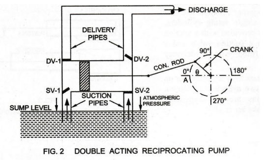
Working Principle
See Fig. 2. If the liquid is in contact with
both the sides of the piston, it is known as Double Acting Reciprocating Pump.
A double acting reciprocating pump has two suction and two delivery pipes. The
corresponding two Suction Valves (SV1, and SV2) and two
Delivery Valves (DV1, and DV2) are as shown.
During
each stroke, when suction takes place on one side of the piston, the other side
delivers the liquid. In this way, in the case of a double acting pump, in one
complete revolution of the crank, there are two suction strokes and two
delivery strokes. Therefore, the liquid is delivered by the pump during these
two delivery strokes.
• Work Done by Double Acting
Reciprocating Pump
In this, when there is a suction stroke on one
side of the piston, its other side has a delivery stroke. Thus, for one
complete revolution of the crank, there are two delivery strokes. The liquid is
delivered by the pump during these two delivery strokes.
If
the speed of the crank is N rpm, then the number of delivery strokes will be 2N
per minute or (N/ 30 ) per second. However, due to the presence of the piston
rod on one side, the volume of liquid delivered from both sides of the piston
will not be equal.
Basic Civil & Mechanical Engineering: UNIT IV: f. Pumps : Tag: : - Reciprocating Pumps - Classification According to the contact of liquid with one side or both sides of the piston
Related Topics
Related Subjects

Basic Civil and Mechanical Engineering
BE3255 2nd Semester 2021 Regulation | 2nd Semester EEE Dept 2021 Regulation