Microprocessors and Microcontrollers: Unit III: (c) 8051 I/O Ports, Timer, Serial Port & Interrupts
8051 Counter Programming
When the timer/counter is used as a counter, the TMOD, TH and TL registers are used, functioning the same as for the timer studied in the last section.
8051 Counter Programming
When
the timer/counter is used as a counter, the TMOD, TH and TL registers are used,
functioning the same as for the timer studied in the last section.
![]() Bit in TMOD Register : As seen earlier, the
Bit in TMOD Register : As seen earlier, the ![]() bit
in the TMOD register decides the timer/counter functioning as a counter or a
timer. When
bit
in the TMOD register decides the timer/counter functioning as a counter or a
timer. When ![]() bit in the TMOD register is 0, the timer mode is
selected. When timer/counter is used as a timer, the 8051's crystal is used as
a source of the frequency. When
bit in the TMOD register is 0, the timer mode is
selected. When timer/counter is used as a timer, the 8051's crystal is used as
a source of the frequency. When ![]() bit in the TMOD register is 1, the
counter mode is selected. When timer/counter is used as a counter, it gets its
pulses from outside the 8051. The pin P 3.4 (pin number 14) and pin 3.5 (pin
number 15) of 8051 are used for applying pulses counter 0 and counter 1
respectively. These two pins belong to port 3. The counter counts up for each
clock pulse applied at this pin. These pins are called T0 (timer 0 clock input)
and Tl(timer 1 clock input).
bit in the TMOD register is 1, the
counter mode is selected. When timer/counter is used as a counter, it gets its
pulses from outside the 8051. The pin P 3.4 (pin number 14) and pin 3.5 (pin
number 15) of 8051 are used for applying pulses counter 0 and counter 1
respectively. These two pins belong to port 3. The counter counts up for each
clock pulse applied at this pin. These pins are called T0 (timer 0 clock input)
and Tl(timer 1 clock input).
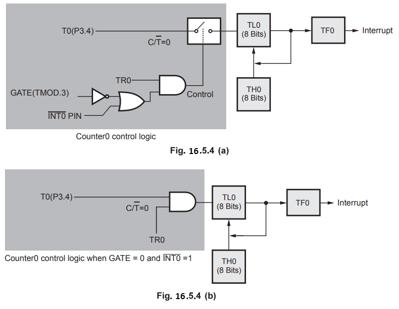
Counter
0 in Mode 1 : The Fig. 16.5.1 (a) shows the block
diagram of counter 0 in mode 1 and the Fig. 16.5.1 (b) shows the block diagram
of counter 0 in mode 1 when GATE = 0 and ![]() = 1. Here, counter 0 counts up
when the logic signal on pin T0 goes from high level to low level.
= 1. Here, counter 0 counts up
when the logic signal on pin T0 goes from high level to low level.

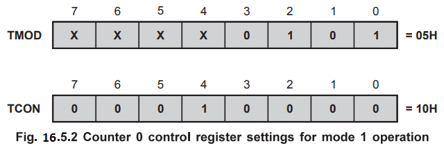
To
operate counter 0 in mode 1 we have to perform following steps :
1. ![]() bit in TMOD register (Bit 2) is set to 1 to allow counter mode operation.
bit in TMOD register (Bit 2) is set to 1 to allow counter mode operation.
2.
M1 : M0 bits (bits 1 : 0) in TMOD register are set to 01 to select mode 1.
3.
When Gate bit (Bit 3) in TMOD register is cleared to 0, TR0 bit (bit 4 of TCON)
is set to 1 to start the counter.
4.
When Gate bit (Bit 3) in TMOD register is set to 1, counter will run only if
TR0 is set to 1 and the logic signal on external interrupt pin ![]() is high.
is high.
Counter
1 in Mode 1 : The Fig. 16.5.3 (a) shows the block
diagram of counter 1 in mode 1 and the Fig. 16.5.3 (b) shows the block diagram
of counter 1 in mode 1 when GATE = 0 and ![]() = 1.
= 1.
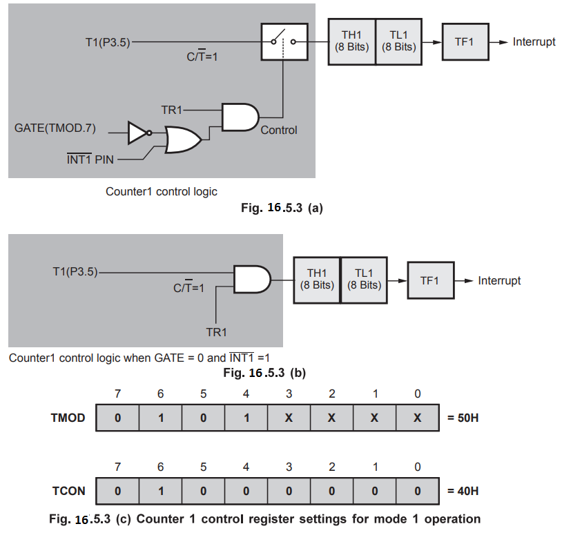
The
operation of counter 1 in mode 1 is same as counter 0 operation. The only
difference is that here registers for counter 1 are programmed instead of
counter 0.
Counter
in Mode 2 : In this mode, counter is used in
auto-reload mode instead of 16-bit counter. Rest of the operation is exactly
same as that of Mode 1. The Fig. 16.5.4 (a) shows the block diagram of counter
0 in Mode 2 and the Fig. 16.5.4 (b) shows the block diagram of counter 0 in
Mode 2 when GATE = 0 and ![]() = 1
= 1
Example
16.5.1 Write a program for counter 1 in mode 2 to count
the pulses and display the state of TL1 count on port 2. Assume that clock
input is connected to T1 pin (P 3.5).
AU
: Dec.-12, Marks 8
Solution
:
MOV
TMOD, #01100000B ; Initialize counter 1 in Mode 2, ![]() = 1
= 1
MOV
TH1, #0 ; Clear TH1
SETB
P3.5 ; Make T1 input
START
: SETB TR1 ; Start the counter
BACK
: MOV A, TL1 ; Get the count from TL1
MOV
P2, A ; Sent it to port 2
JNB
TF1, BACK ; If TF1 = 0 repeat
CLR
TR1 ; Otherwise stop counter 1
CLRTF1
; Make TF1=0
SJMP
START ; Repeat
Note
When 8051 is powered up ports are configured as input ports. To make them work
as output port we have to send high output on it. Therefore, to behave T1 as
input P 3.5 is set.
Example
16.5.2 Write a program to display counter 0 on 7-segment
LEDs. Assume that clock input is connected to pin (P 3.4).
Solution
:
MOV
TMOD, #00000110 ; Initialize counter 0 in Mode 2, C/T=1
MOV
THO, #00H ; Reset counter value
SETB
P3.4 ; Make T0 as input
START:
SETB TR0 ; Start counter 0
BACK:
MOV A, TL0 ; Get the count value
ACALL
CONVBCD
MOV
P2, A ; Send count value in BCD on port 2
JNB
TF0, BACK ; If TF0 = 0 repeat
CLR
TR0 ; Otherwise stop counter 0
CLR
TF0 ; Make TF0=0
SJMP
START ; Repeat
CONVBCD:
ADD A, #00H ; [Use DAA for
DA
A ; BCD conversion]
RET
; Return to main program
Example
16.5.3 Assume that XTAL = 11.0592 MHz. Write a program to
generate a square wave of 2 kHz frequency on pin P1.5.
Solution
:
T = 1 /f = l/2 kHz = 500 µs is period of square wave. 1/2 of it for high and low
portion of the pulse is 250 µs. 250 µs/1.085 µs = 230 and 65536 - 230 = 65306
which in hex is FF1AH.
ஃ TL = 1AH and TH = FFH
Program
is as follows
MOV
TMOD, #10H ; timer 1, mode 1
AGAIN
: MOV TL1, #1AH ; low byte of timer
MOV
TH1, #0FFH ; high byte of timer
SETB
TR1 ; Start timer 1
BACK
: JNB TF1, BACK ; Stay until timer rolls over
CLR
TR1 ; Stop timer 1
CPL
P1.5 ; Complement P1.5
CLR
TF1 ; Clear timer flag
SJMP
AGAIN ; reload timer
Example
16.5.4 Generate a square wave of frequency 1 kHz using
timer 1 in mode 1, on Pin P1.2. Explain the TMOD word used to configure the
timer 1 for this application. Show the necessary calculations to find the value
of count to be loaded into TH1 and TL1 registers. Assume XTAL frequency -
11.0592 MHz.
Solution
:
T
of square wave = 1/f = 1/2 kHz = 500 µs
ஃ Count to be loaded in TH1 and TL1 =
65536 - 230 = 65306 = FF1AH
ஃ TH1 = FF and TL1 = 1AH
Program
MOV
TMOD, #10H ; Timer 1, mode 1 (16-bit)
AGAIN
: MOV TL1, #1AH ; Load lower byte of timer
MOV
TH1, #0FFH ; Load higher byte of timer
SETB
TR1 ; Start timer 1
BACK
: JNB TF1, BACK ; Wait for timer rolls over
CLR
TR1 ; Stop timer 1
CPL
P1.2 ; Complement P1.2
CLR
TF1 ; Clear timer flag 1
SJMP
AGAIN ; Reload timer 1 and continue
Example
16.5.5 Explain the steps to program timers in model and
write an 8051 program to generate a square wave of 50 % duty cycle on the pin P1.5.
Solution
: Square
wave
MOV
TMOD, #01 ; Timer 0 mode 1
Here
: MOV TL0, #0F2H ; Load TL0 - 0F2
MOV
TH0, #0FFH ; Load TH0 - 0FF
CPL
P1.5 ; toggle input on P1.5
ACALL
Delay
SJMP
Here
Delay
: SETB TR0 ; Start Timer 0
again
: JNB TF0, again ; Monitor Timer 0 flag until it rolls over
CLR
TRO
CLR
TF0
RET
Example
16.5.6 Write an ALP to generate square wave on pin Pl.5
of 500 Hz (approximately) with a subroutine to provide a time delay of 30.38 is
using timer 0. Assume that crystal frequency of 8051 is 11.0592 Hz.
Solution
:
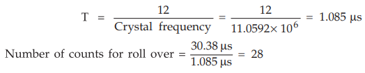
65536
- 28 = 65508 = FFE4H
ஃ
To
get a delay of 30.38 we have to load TH0 = FFH and TL0 = E4H
For
square wave T = 1/500 = 2 ms
ஃ
TON
= TOFF = T/2 = 1 ms
Thus
we have call delay routine (1 ms/30.38 µs) = 33 = 21H times
Program
MOV
TMOD, #01 ; Timer0, mode1
HERE
: MOV TL0, #E4H ; Load TL0 = E4H
MOV
TH0, #FFH ; Load TH0 = FFH
CPL
P1.5 ; toggle P1.5
MOV
R0, #21H ; Load count in R0
BACK
: ACALL Dealy ; wait for 30.38 µs × 33 = 1ms
DJNZ
R0, BACK
SJMP
HERE
DELAY
: SETB T0 ; start timer 0
AGAIN
: JNB TF0, AGAIN ; Wait for TF0 to roll over
CLR
TR0 ; stop timer 0
CLR
TF0 ; Clear TF0
RET
; Return
Example
16.5.7 Find the delay generated by timer 0 in the
following code. Calculate the delay generated excluding the instruction
overhead. What count has to be loaded in TL0 and TH0 if delay has to be increased
to 25 msec ?
CLR
P2.3
HERE
: MOV TMOD, #01
MOV
TL0, #3Eh
MOV
TH0, #0B8h
SETB
TF0
AGAIN:
JNB TF0, AGAIN
CLR
TF0
CLR
TR0
CLR
P2.3
Solution
:
Timer
count = B83E
(FFFF
- B83E + 1) = 47C2H = (18370)10
Assuming
XTAL = 11.0592 MHz
T
= 12 / 11.0592 × 106 = 1.085 × 10⁻⁶
ஃ Delay = 1.085 × 10- 6 ×
18370 = 19.93 ms
For
25 msec delay
Decimal
count = 25 ms / 1.085 × 10-6
= 23041
=
5A01 H
ஃ
TL0
= 01H and TH0 = 5AH
Example
16.5.8 Find out Hex. number to be loaded in TH0, to
produce delay of 4.096 msec in mode 'O' operation. Assume clock frequency of 12
MHz.
Solution
:
Timer clock frequency = Crystal frequency + 12 =12 MHz + 12
= 1 MHz
ஃ
Timer clock period = 1 µs
Maximum
count in mode 0 is 1FFFH (8191) and we have to count for 4096 counts to get a
delay of 4.096 ms
ஃ
Count
to be loaded in timer is 1FFFH
(8191
in decimal) - 4096 = FFFH (4095 in decimal)
Therefore,
we have to load 0FH in TH0 and FFH in TL0.
Example
16.5.9 Using autoreload mode of timer 0 in 8051, generate
a frequency of 10 kHz on pin P1.0. Write assembly language program for it.
Solution
:
Assume XTAL frequency = 12 MHz. To generate a frequency of 10 kHz, one half of
the cycle is of period 0.05 ms. Since XTAL frequency = 12 MHz we have cycle
period is Ips. Therefore, we have to decrement count equal to 50. Thus the
initial value to be loaded in TH0 = (256 - 50) = 206.
Program
MOV
TMOD, #2H ; Timer 0, mode 2 (8-bit auto reload)
MOV
TH0 #206 ; TH0 = 206
SETB
TR0 ; Start timer 0
BACK
: JNB TF1 BACK ; Stay till timer rolls over
CPL
P1.0 ; Complement P1.0
CLR
TF0 ; Clear timer flag 0
SJMP
BACK ; Continue
Example
16.5.10 Write an assembly language program to make LED
ON and OFF connected to P 1.0 continuously with ON time 20 msec and off time 40
msec.
Solution
:
Assume crystal frequency 12 MHz
Time
for one instruction = (1/12MHz)* 12 = 1 µsec.
Count
to be loaded in TH0:TL0 = >20 µsec / 1 p sec. = 20000 (Decimal)
65536
- 20000 = 45536 = B1E0H
ORG
0000H
START
: MOV TMOD,#01H
MOV
TH0,#0B1H
MOV
TL0,#0E0H
SETB
P1.0
ACALL
DELAY
CLR
P1.0
ACALL
DELAY
ACALL
DELAY
SJMP
START
DELAY20MS
: SETB TR0
HERE
: JNB TF0, HERE
CLR
TF0
CLR
TF0
RET
Example
16.5.11 Write an assembly language program to
generate a square wave of frequency 5 kHz on pin P3.0 using auto reload mode of
timer 0 in 8051.
Solution
:
For 5 kHz T = 1/5 kHz = 200µs and T/2 = 100 µs
Assume
clock frequency 12 MHz so time for one cycle is 1 µs. So the value of TH0 and
TL0 is 255 - 100 = 155
ORG
0000H
MOV
TMOD, #02H ; Timer 0 in mode 2
MOV
TH0,#155 ; TH0 = 155
SETB
TR0 ; Start timer 0
HERE
: JNB TF0, HERE
CPL
P3.0
ORG
001BH
CLR
TF0
SJMP HERE
1. Programming Timers in 8051 C
The
general purpose registers of 8051, such as R0-R7, A and B are under control of
the C compiler and are not accessed directly by C statement. However, in case
of SFRs entire RAM space of 80H-FFH is directly accessible to 8051 C
statements. In this section we discuss the accessing of timers using C
statements.
Accessing
Timer Registers in C
In
8051 C, we can access the timer registers TH, TL and TMOD directly with the
inclusion reg51.h file in the program. We can also access TR and TF bits
directly. This is illustrated in example.
Example
16.5.12 Write an 8051 C program to toggle all bits
of port P0 continuously. Use timer 0 to generate delay of 1 sec between each
toggle.
Solution
:
#include
<reg51.h>
void
DELAY (void);
void
main (void)
{
while(1)
/* Repeat forever */
{
P0=0x00
; /* Make P0 bits all zero */
DELAY();/*
Wait for 1 sec */
P0
= 0xFF; /* Make P0 bits all one */
DELAY();/*
Wait for 1 sec */
}
}
void
DELAY()
{
unsigned
char i;
for(i=0;
i<20; i++)
{
TMOD
= 0x01; /* Configure timer 0 in mode 1 */
TL0
= 0x28; /* Load count in TL0*/
TH0
= 0x29; /* load count in TH0 */
TR0
= 1; /* Turn on T0 */
while(TF0
= = 0); /* Wait for TF0 to rollover */
TR0
= 0; / turn off T0 */
TF0
= 0; /* clear TF0 */
}
}
Timer
Count Calculations
Assume
crystal frequency = 12 MHz
ஃ T = 12
/ 12 × 10-6 = 1 µs
Let
us determine the count to get a delay of 50 ms
ஃ
We need 50 ms / 1 µs = 50000 clocks.
ஃ
Count
= 65536 - 50000 = 10536 = 2928 H
To
get a delay of 1 sec we have to repeat the delay of timerO 20 (1/50 msec)
times.
Example
16.5.13 Write an 8051 C program to toggle only
pin P1.0 continuously every 500 ms.
Solution
:
Let
us use mode 2 of timer0 to create the delay. Mode 2 is an 8-bit auto reload
mode.
#include
<reg51.h>
void
Delay(void);
sbit
portbit = P1 ^ 0;
void
main(void)
{
unsigned
char i,j;
while(1)
{
portbit
= ~ portbit; /* toggle P1.0 */
for(i=0;
i<500; i++)
for(j=0;
j<40; j++)
Delay();
}
}
void
Delay(void)
{
TMOD=0x02;
/* Time 0, mode 2(8-bit auto-reload) */
TH0=-25;
/* load TH0 (auto-reload value) */
TR0=l;
/* turn on TO */
while
(TF0==0); /* wait for TF0 to roll over */
TR0=0;
/* turn off TO */
TF0=0;
/* clear TF0 */
}
Delay
calculations : Assume XTAL frequency = 12 MHz.
T
= 12/12 MHz = 1 µs
256
- 25 = 231
25
× 1.0 µs = 25 µs
Total
delay = 25 µs × 500 × 40 = 500 ms
Note
Due
to inclusion of for loop of C in delay generation, the delay may be slightly
more than expected. To get a correct delay we can adjust delay loop count by
observing frequency of port 1.0 on oscilloscope.
Example
16.5.1 Write an 8051 C program to create a frequency of 2
kHz on pin P2.0.
Solution
:
Let us use mode 2 of timerl to create the delay. Mode 2 is an 8-bit auto reload
mode.
#include
<reg51.h>
void
Delay (void);
sbit
portbit=P2 ^ 0;
void
main(void)
{
while(1)
{
portbit=~portbit;
/* toggle P2.0 */
Delay();
}
}
void
Delay(void)
{
TMOD=0x20;
/* Timer 1, mode 2(8-bit auto-reload) */
TH1=-250;
/* load Thl (auto-reload value) */
TR1
= 1; /* turn on T1 */
while(TF1
= =0); /* wait for TF1 to roll over */
TR1=0;
/* turn off T1 */
TF1=0;
/* clear TF1 */
}
Delay
calculations : Assume XTAL frequency = 12 MHz
T
= 12/12 MHz = 1 µs
1/2
kHz = 0.5 ms
0.5
ms/2 = 0.25 ms
0.25
ms / 1 µs = 250
Example
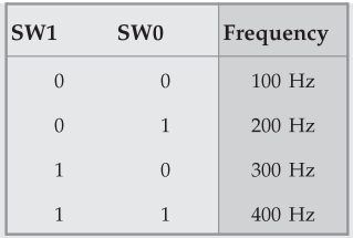
16.5.15 Two switches are connected to pin P1.0
and Pl.l, respectively. Write an 8051
C program to monitor switches and create the following frequencies on pin P2.0
according switch positions.
Solution
:
#include
<reg51.h>
sbit
sw0=P1^0;
sbit
sw1= P1^1;
sbit
portbit=P2 ^ 0;
void
Delay (unsigned char);
void
main(void)
{
SW0=1;
/* Make P1.0 an input */
SW1
= 1; /* make P1.1 an input */
while(1)
{
portbit=~portbit;
/* toggle P2.0 */
if(sw1=
=0&sw0= =0) /* check switch */
Delay(1);
if(sw1
= =0&sw0= = l)
Delay(2);
if(sw1=
= 1&sw0==0)
Delay(3);
if(sw1
= = 1&SW0= = 1)
Delay
(4);
}
}
void
Delay(unsigned char c)
{
TMOD=0x01;
do
{
TL0=0x78;
TH0=0xEC;
TR0=l;
while
(TF0==0);
TR0=0;
TF0=0;
c=c-l;
}
while(c!=0);
}
EC78H
= 60536
65536
- 60536 = 5000
5000
× 1 µs = 5 ms
1
/ (5 ms × 2) = 100 Hz
C
Programming of Timers 0 and 1 as Counters
Let
us see how to use timers 0 and 1 as event counters. A timer can be used as a
counter if we provide external clock instead of using the frequency of the
crystal oscillator as the clock source. By feeding pulses to the TO (P3.4) and
T1 (P3.5) pins, we can use timer 0 and timer 1 as counter 0 and counter 1,
respectively. Following examples show us how timers 0 and 1 are programmed as
counters using the C language.
Example
16.5.16 Assume that a 1-Hz external clock is being fed
into pin Tl. Write a C program for counter 1 in mode 2 (8-bit auto reload) to
count up and display the state of the TL1 count on P0. Start the count from 00H.
Solution
:
#include <reg51.h>
Sbit
T1 = P3^5;
Void
main(void)
{
T1=1;
/* make T1 an input */
TMOD=0x60;
TH1=0;
/* set count to 0 */
While(1)
/* repeat forever */
{
TR1=1
/* start timer */
do
{
P0=TL1;
/* place value on port P0 */
}
while
(TF1 = = 0); /* wait for TF1 to rollver */
TR1=
0; /* stop timer */
TF1
= 0; /* clear flag */
}
}
Example
16.5.17 Assume that a 1 Hz external clock is being fed
into pin TO. Write a C program for counter 0 in mode 1 (16 bit) to count the
pulses and display the TH0 and TL0 registers on P1 and P0, respectively.
Solution
:
#include
<reg51.h>
void
main(void)
{
T0=l; /* make T0 an input */
TMOD=0x05;
TL0=0; /* set count to 0 */
TH0=0; /* set count to 0 */
while(1) /* repeat forever */
{ TR0=1; /*
start timer */
do
{
P0=TL0;
/* place value of TL0 on port 0 */
P1=TH0;
/* place value of TH0 on port 1 */
}
while(TF0==0);
/* wait here */
TR0=0; /* stop timer */
TF0=0; /*clear flag */
}
}
Example
16.5.18 Assume that a 2 Hz external clock is being fed
into pin T1. Write a C program for counter 0 in mode 2 (8-bit auto reload) to
display the count in ASCII. The 8-bit binary count must be converted to ASCII.
Display the ASCII digits (in binary) on PO serially. Display least significant
digit first.
Solution
:
To display the TL1 count we must convert 8 bit binary data to ASCII.
#include
<reg51.h>
void
BinToASCn(unsigned char);
void
main()
{
unsigned
char value;
T1=l;
TMOD=0x06;
TH0=0;
while(1)
{
do
{
TR0=1;
value=TL0;
BinToASCII(value);
}
while
(TF0==0);
TR0=0;
TF0=0;
}
}
void
BinToASCII (unsigned char value)
unsigned
char Abyte, i,Q;
unsigned
char R[3];
Abyte
= 0XFB;
i=0;
do
{
Q=Abyte/10;
/* divide by 10 */
R[i]=Abyte%10;
/* find remainder and save it */
Abyte=Q;
/* save quotient as a number */
i
= i+1;
}
while(Q!=
0) /* Repeat until quotient = 0 */
for(;
i>0 ; i- -)
{
P0=R[i-1]+0×30;
/* Make binary to ASCII */
}
}
Example
16.5.19 Assume that a 100 Hz external clock is
being fed into pin TO. Write a C program for counter 0 in mode 2 (8-bit
auto-reload) to display the seconds and minutes on P0 and P1, respectively.
Solution
:
#include
<reg51.h>
void
Time(unsigned char);
void
main(void)
{
unsigned
char val=0;
T0=l;
TMOD=0x06;
/* TO, mode 2, counter */
TH0=100;
/* sec=100 pulses */
while(1)
{
TR0=1; /* start timer */
while
(TF0==0);
Time(val);
val+
+ ;
TR0=0;
/* stop timer */
TF0=0;
/* clear flag */
}
}
void
Time(unsigned char value)
{
unsigned
char sec.min;
min=value/60;
sec=value
% 60;
P0=sec;
P1=min;
}
Example
16.5.20 Write an 8051 C program to generate a
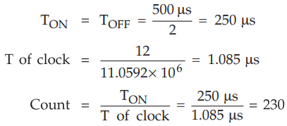
rectangular wave of 2 kHz with 60 % duty cycle in pin P1.2. Assume crystal
frequency as 11.0592 MHz. Use Timer - 0 in mode-1 operation. Show delay
calculations.
Solution
:
For 2 kHz rectangular wave,
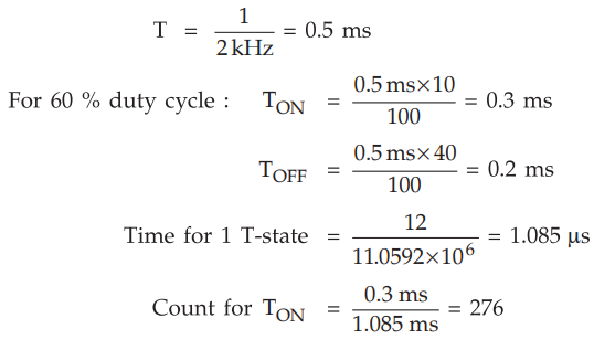
Count
for TOFF = 184
Count
to be loaded for TON = 65536 - 276 = 65260 = FEECH
TH0
= FEH, TL0 = ECH
Count
to be loaded for TOFF = 65536 - 184 = 65352 = FF48H
TH0
= FFH, TL0 = 48H
#include
<reg51.h>
sbit
mybit = P2^1;
void
T0M1D (unsigned char) ;
void
main (void)
{
while
(1)
{
mybit
= 1; /*Make P2.1 High*/
T0M1D
(1); /* Wait for 0.3 msec */
mybit
= 0; /*Make P2.1 Low*/
T0M1D
= (0); /*Wait for 0.2 msec*/
}
}
void
T0M ID (unsigned char i)
{
TMOD
= 0 × 01; /*Timer 0, mode 1*/
if
(i = = 0)
{
TL0
= ECH; /*Load FEECH*/
TH0
= FEH;
}
else
{
TL0
= 48H; /*Load FF48H*/
TH0
= FFH;
}
TR0
= 1; /*Turn ON Timer 0*/
while
(TF0 = = 0); /Wait for TF0 to roll over */
TR0
= 0; /*Turn OFF Timer 0 */
TF0
= 0; /*Clear TF0*/
}
Review Question
1. Write a note on
counter programming of 8051.
Microprocessors and Microcontrollers: Unit III: (c) 8051 I/O Ports, Timer, Serial Port & Interrupts : Tag: : - 8051 Counter Programming