Microprocessors and Microcontrollers: Unit III: (c) 8051 I/O Ports, Timer, Serial Port & Interrupts
8051 Serial Port
The serial port of 8051 is full duplex, means it can transmit and receive simultaneously. It uses register SBUF to hold data.
8051 Serial Port
The
serial port of 8051 is full duplex, means it can transmit and receive
simultaneously. It uses register SBUF to hold data. Register SCON controls data
communication, register-PCON controls data rates and pin R×D (P3.0) and T×D
(P3.1) do the data transfer.
SBUF
is an 8-bit register dedicated for serial communication in 8051. Its address is
99H. It can be addressed like any other register in 8051. Writing to SBUF loads
data to be transmitted and reading SBUF accesses received data. There are two
separate and distinct registers, the transmit write-only register, and the
receive read-only register. This is illustrated in Fig. 16.6.1.

The
way in which SBUF is used for the transmission and reception of the data during
serial communication is explained below.
•
Transmission : When a byte of data is to be
transmitted via the T×D pin, the SBUF is loaded with this data byte. As soon as
a data byte is written into SBUF, it is framed with the start and stop bits and
transmitted serially via the T×D pin.
•
Reception : When 8051 receives data serially via R×D
pin of it, the 8051 deframes it. The start and stop bits are separated out from
a byte of data. This byte is placed in SBUF register.
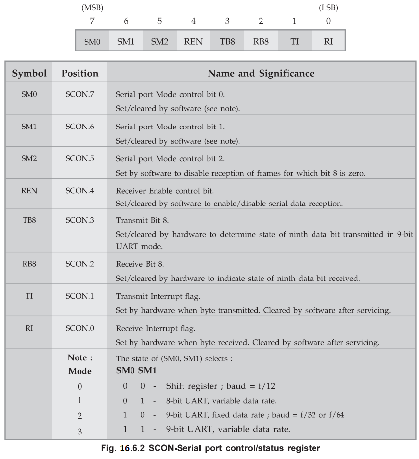
Bit
pattern of SCON register : The 8051 provides four
programmable modes for serial data communication. A particular mode can be
selected by setting the SMO and SMI bits in SCON. The mode selection also decides
the baud rate. The Fig. 16.6.2 shows the bit patterns for SCON.
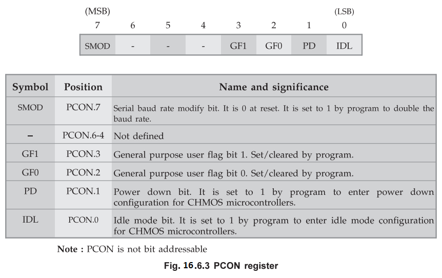
Bit pattern of PCON register :
1. Operating Modes for Serial Port
Mode
0 :
In this mode, serial data enters and exits through RxD. TxD outputs the shift
clock. 8 bits are transmitted/received : 8 data bits (LSB first). The baud rate
is fixed at 1/12 the oscillator frequency.
Mode
1 : In
this mode, 10 bits are transmitted (through TxD) or received (through RxD): A
start bit (0), 8 data bits (LSB first) and a stop bit (1). On receive, the stop
bit goes into RB8 in Special Function Register SCON. The baud rate is variable.
Mode
2 :
In this mode, 11 bits are transmitted (through TxD) or received (through RxD):
A start bit (0), 8 data bits (LSB first), a programmable 9th data bit, and a
stop bit (1). On Transmit, the 9th data bit (TB8 in SCON) can be assigned the
value of 0 or 1. Or, for example, the parity bit (P, in the PSW) could be moved
into TB8. On receive, the 9th data bit goes into RB8 in Special Function
Register SCON, while the stop bit is ignored. The baud rate „ programmable to
either 1 / 32 or 1 / 64 the oscillator frequency.
Mode
3 :
In this mode, 11 bits are transmitted (through TxD) or received (through RxD):
A start bit (0), 8 data bits (LSB first), a programmable 9th data bit and a
stop bit (1). In fact, Mode 3 is the same as Mode 2 in all respects except the
baud rate. The baud rate in Mode 3 is variable.
In
all four modes, transmission is initiated by any instruction that uses SBUF as
a destination register. Reception is initiated in Mode 0 by the condition RI =
0 and REN = 1. Reception is initiated in the other modes by the incoming start
bit if REN = 1.
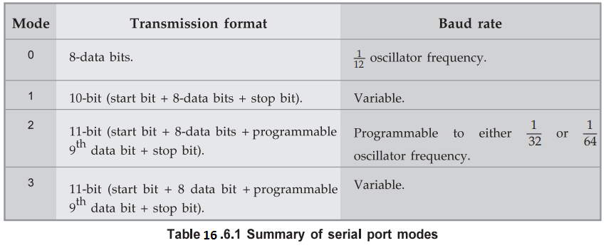
The
Table 16.6.1 summarizes the four serial port modes provided by 8051.
2. Generating Baud Rates
Serial
Port in Mode 0 Mode 0 has a fixed baud rate which is 1/12 of the oscillator
frequency. To run the serial port in this mode none of the Timer/Counters need
to be set up. Only the SCON register needs to be defined.
Baud
rate = Oscillator frequency / 12
Serial
Port in Mode 1: Mode 1 has a variable baud rate. The
baud rate can be generated by either Timer 1 or Timer 2 (8052 only).
Using
Timer/Counter 1 to Generate Baud Rates
For
this purpose, Timer 1 is used in mode 2 (Auto-Reload).
Baud
rate = K × Oscillator frequency / 32 × 12 × [(256-TH1)]
If
SMOD = 0, then K = 1.
If
SMOD = 1, then K = 2. (SMOD is the PCON register)
Most
of the time the user knows the baud rate and needs to know the reload value for
TH1. Therefore, the equation to calculate TH1 can be written as :
TH1
= 256 = K × Oscillator frequency / 384 × Baud rate
TH1
must be an integer value. Rounding off TH1 to the nearest integer may not
produce the desired baud rate. In this case, the user may have to choose
another crystal frequency.
Since
the PCON register is not bit addressable, one way to set the bit is logical
ORing the PCON register, (i.e. ORL PCON, #80H). The address of PCON is 87H.
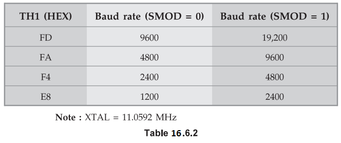
The
Table 16.6.2 shows the values to be loaded into TH1 to get the corresponding
baud rate. It also shows that the baud rates are doubled when SMOD = 1.
Using
Timer/Counter 2 to Generate Baud Rates
For
this purpose, Timer 2 must be used in the baud rate generating mode. If Timer 2
is being clocked through pin T2 (P1.0) the baud rate is :
Baud
rate = Timer 2 overflow rate / 16
And
if it is being clocked internally the baud rate is :
Baud
rate = Oscillator frequency / 32 × [65536 - (RCAP2H, RCAP2L)]
To
obtain the reload value for RCAP2H and RCAP2L the above equation can be rewritten
as :
RCAP2H,
RCAP2L = 65536 - Oscillator frequency / 32 × Baud rate
Serial
Port in Mode 2
The
baud rate is fixed in this mode and is 1/32 or 1/64 of the Oscillator frequency
depending on the value of the SMOD bit in the PCON register. In this mode none
of the Timers are used and the clock comes from the internal phase 2 clock.
SMOD
= 1, Baud rate = 1/32 Oscillator frequency
SMOD
= 0, Baud rate = 1 / 64 Oscillator frequency
To
set the SMOD bit : ORL PCON, #80H. The address of PCON is 87H.
Note
By changing SMOD bit in PCON from 0 to 1 we can double the baud rate in 8051.
Serial
Port in Mode 3
The
baud rate in mode 3 is variable and sets up exactly the same as in mode 1.
3. Programming 8051 for Serial Data Transfer
To
program 8051, to transfer data serially we have to perform following sequence
of actions :
1.
Load the TMOD register with the value 20H to use timer 1 in mode 2 (8-bit
auto-reload) to set the baud rate.
2.
Load TH1 to set the desire baud rate for serial data transfer.
3.
Load SCON register with the value 50H, to use serial mode 1, where an 8-bit
data is framed with start and stop bits.
4.
Set TR1 to 1 to start timer 1.
5.
Clear TI with CLR TI instruction.
6.
Write a character to be sent in to the SBUF register.
7.
Check the TI flag bit with instruction JNB TI, XXXX to see if the character has
been transferred completely.
8.
Go to step 5 to transfer the next character.
Example
17.6.1 8051 uses 11.0592 MHz crystal. To get 9600 hertz
baud rate how will you program it for serial transmission ?
Solution:
When 11.0592 MHz crystal is used and a standard baud rate of 9600 hertz is
required then, the setting of TH1 can be found as,
TH1
= 256 - k × Oscillator frequency / 384 × Baud rate
=
256 - 1 × 11.0592 × 106 / 384 × 9600 = 253 = FDH
Program:
MOV TMOD, #020 ; Initialize timer 1 in mode 2
MOV
SCON, #4CH ; Initialize serial mode 1
ORL
PCON, #80H ; Make SMOD = 1
MOV
TH1, #FDH ; Load count
Example
16.6.2 Write an 8051 assembly language program to
transfer letter "A" serially at 9600 baud rate, continuously.
Solution
:
MOV
TMOD, #20H ; timer 1, mode 2 (auto reload)
MOV
TH1, #FDH ; 9600 baud rate
MOV
SCON, #50H ; 8-bit, 1 stop REN enabled
SETB
TR1 ; start timer 1
START:
MOV SBUF, #"A" ; Letter "A" to be transferred
HERE:
JNB TI, HERE ; Wait for the last bit to transfer
CLR
TI ; Clear TI for the next character
SJMP
START ; Go to send the character again
Example
16.6.3 Write an 8051 assembly language program to transfer
the message "HELLO "serially at 9600 baud, 8-bit data, 1 stop bit.
Solution
:
MOV
TMOD,#20H ; timer 1, mode 2
MOV
TH1,#FDH ; 9600 baud rate
MOV
SCON,#50H ; 8-bit, 1 stop bit, REN enabled
SETB
TR1 ; start timer 1
START:
MOV A, #"H" ; transfer "H"
ACALL
TRANS
MOV
A, #"E" ; transfer "E"
ACALL
TRANS
MOV
A, #"L" ; transfer "L"
ACALL
TRANS
MOV
A, #"L" ; transfer "L"
ACALL
TRANS
MOV
A,#"O" ; transfer "O"
ACALL
TRANS ; Serial data transfer subroutine
TRANS:
MOV SBUF, A ; Load SBUF
HERE:
JNB TI, HERE ; wait for the last bit to transfer
CLR
TI ; Clear TI for the next character
RET
The
importance of the TI flag bit :
When
a data is to be transmitted via TxD pin, first a data byte is loaded into the
SBUF register. A start bit, a data byte and then the stop bit are transmitted
sequentially via TxD pin. During the transmission of the stop bit, 8051 sets
the TI flag, i.e. TI = 1. This indicates the end of data byte transmission and
8051 is ready for the transmission and 8051 is ready for the transmission of
next data. The programmer has to clear the TI flag, i.e. TI = 0, with the 'CLR
TI' instruction to transmit next data. The TI flag bit should be monitored to
make sure that the SBUF register is not overwritten. If we write the next byte
to be transmitted into the SBUF register before setting the TI flag bit, the
untransmitted portion of the previous byte will be lost. The programmer can
check the TI flag bit by 'JNB TI, XX' instruction or by using an interrupt.
4. Programming 8051 for Receiving Data Serially
To
program 8051, to receive data serially we have to perform following sequence of
actions :
1.
Load the TMOD register with the value 20H to use timer 1 in mode 2 (8-bit
auto-reload) to set the baud rate.
2.
Load TH1 to set the desire baud rate for serial data transfer.
3.
Load SCON register with the value 50H, to use serial mode 1, where an 8-bit
data is framed with start and stop bits.
4.
Set TRI to 1 to start timer 1.
5.
Clear RI with CLR RI instruction.
6.
Check the RI flag bit with instruction JNB RI, XXXX to see if an entire
character has been received yet.
7.
If RI is set, SBUF has the byte. Save this byte.
8.
Go to step 5 to receive the next character.
Example
16.6.4 Write an 8051 assembly language program to
receive bytes serially with baud rate 9600, 8-bit data and 1 stop bit.
Simultaneously send received bytes to port 2.
Solution
:
MOV
TMOD, #20H ; timer 1, mode 2 (auto reload)
MOV
TH1, #FDH ; 9600 baud rate
MOV
SCON, #50H ; 8-bit, 1 stop, REN enabled
SETB
TR1 ; start timer 1
HERE:
JNB RI, HERE ; wait for character receive completely
MOV
A, SBUF ; save the received character
MOV
P2, A ; send character to port 2
CLR
RI ; Get ready to receive next byte
SJMP
HERE ; Go to receive next character
The
importance of the RI flag bit : When a data is to be
received via RxD pin, first the start bit, and a data byte with one bit at time
are received sequentially via RxD pin. When the last bit of a data byte is
received, a byte is formed and the SBUF register is loaded with this byte. Then
the stop bit is received. During the reception of the stop bit, 8051 sets the
RI flag, i.e. RI = 1. This indicates that the entire data byte has been
received. This data byte which is loaded in the SBUF register, should be placed
to a safe place such as any register or memory before it is lost. The
programmer has to clear the RI flag, i.e. RI = 0, with the 'CLR RI' instruction
to receive next data and place it in SBUF register. The RI flag bit should be
monitored to make sure that the entire byte has been received. This monitoring
of the RI flag bit till it becomes one to ensure the reception of complete data
place it in SBUF register, copy it to the safe place and then make RI zero with
'CLR RI' instruction are the necessary steps to avoid any loss of received
data.
5. Doubling the Baud Rate in the 8051
We
can double the baud rate in 8051 using two way,
•
By doubling the crystal frequency.
•
By making SMOD bit in the PCON register from 0 to 1.
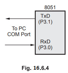
Example
16.6.5 Write a program to receive message from PC to
8051. Message string is "Hello". After this microcontroller sends
message to PC "Fine".
Solution
: The
Fig. 16.6.4 shows the connections between 8051 and PC.
MOV
TMOD, #20H ; Initialize timer 1 in mode 2
MOV
TH1, #0FDH ; Load count to get 9600
;
baud rate
MOV
SCON, #50H ; 8-bit, 1 stop, REN enabled
SETB
TR1 ; Start timer 1
MOV
DPTR, #2000H ; Initialize memory pointer to
;
save received data
MOV
R0,#05H ; Initialize counter to read
;
5 characters
RECV:
JNB RI,RECV ; wait for character
MOV
A,SBUF ; Read the character
MOVX
@DPTR,A ; Save it in memory
INC
DPTR ; increment memory pointer
CLR
RI ; Get ready for next character
DJNZ
R0, RECV ; If not last character repeat
MOV
DPTR, #MYDATA ; Initialize pointer for message
CLR
A
MOV
R0, #4H ; Initialize counter to send 4 characters
MOVC
A, @A+DPTR ; Get the character
MOV
SBUF, A ; Load the data
HERE:
JNB TI,HERE ; Wait for complete byte transfer
CLR
TI ; get ready for next character
6. 8051 Connection to RS 232C
In
RS 232C the voltage level + 3 V to +15 V is defined as logic 0; from - 3 V to
-15 V is defined as logic 1. The control and timing signals are compatible with
the TTL level. Because of the incompatibility of the data lines with the TTL
logic, voltage translators, called line drivers and line receivers, are
required to interface TTL logic with the RS 232C signals. The Fig. 16.6.5 shows
the connection between RS 232C and 8051. Here, MAX 232 chip is used as a line
driver and line receiver. We know that 8051 assigns two pins RxD (P 3.0) and
TxD (P 3.1) for reception and transmission of serial data, respectively. These
pins are TTL compatible; therefore, they require line driver and line receiver
to make them RS 232C compatible. The MAX 232 has two sets of line drivers and
line receivers for transmitting and receiving data. Only one set is required
for one serial communication.

7. Serial Communication Programming in C
The
SFR registers of the 8051 are accessible directly in 8051 C compilers by
inclusion of the reg51.h file. However, to use second serial port we have to
declare the byte addresses of the new SFR registers, i.e. SBUF1 and SCON1 using
SFR data type. In addition, we have to declare bit addresses for Til and RI1
using bit data type.
Example
16.6.6 Write a C program for the 8051 to transfer the
letter "C" serially at 9600 baud continuously. Use 8-bit data and 1
stop bit.
Solution
:
#include
< reg51 .h >
void
main (void)
{
TM0D=
0×20;
TH1
= 0×FD;
SCON
= 0×50;
TRI
= 1;
while(1)
{
SBUF=’C’;
while(TI=
=0);
TI=0;
}
}
Example
16.6.7 Write a C program that continuously receives a
single bit of data from P1.0 and sends if to P2.0, while simultaneously mating
a square wave of 400 ,us period on pin P2.5. Use timer 0 to create the square
wave. Assume that XTAL = 11.0592 MHz.
Solution
:
We will use timer 0 in mode 2 (auto-reload). One half of the period is 200 µs
200/1.085 µs = 184 and TH0 = 256 - 184 = 72 or 48H.
#include
<reg51.h>
sbit
IBit = P1 ^ 0;
sbit
Obit = P2 ^ 0;
sbit
SWAVE = P2 ^ 5;
void timer0(void) interrupt 1
{
SWAVE
= ~ SWAVE; /* toggle pin P2.5*/
}
Void
main(void)
{
Obit
= 1; /* make P1.0 input */
TMOD
= 0×02;
TH0
= 0×82; /* TH0 = -184 */
IE
= 0×82; /* enable interrupts for timer 0 */
While(1)
{
Obit
= Ibit; /* send received bit to P2.0 */
}
}
Example
16.6.8 Write a C program that continuously gets a
single bit of data from P1.0 and sends if to P2.0 in the main, while
simultaneously (a) mating a square wave of 400 ,µs period on pin P2.5, and (b)
sending letter 'A' through 'Z' to the serial port. Use timer 0 to create the
square wave. Assume that XTAL = 11.0592 MHz. Use the 9600 baud rate.
Solution
:
We will use timer 0 in mode 2 (auto-reload). TH0 = 200/1.085 µs = - 184, which
is 72H.
#include
<reg51.h>
sbit
Ibit = P1 ^ 0;
sbit
Obit = P2 ^ 0;
sbit
SWAVE = P2 ^ 5;
unsigned
char ch = ‘A';
void
timer0(void) interrupt 1
{
SWAVE
=~SWAVE; /* toggle pin 2.5 */
}
void
seria10(void) interrupt 4
{
if(TI
== 1)
{
SBUF
= ch; /* send character to serial port */
TI
= 0; /* clear interrupt */
ch+
+ ;
if(ch
>= 'Z')
ch
='A';
}
else
{
RI
= 0; /* clear interrupt */
}
}
void
main(void)
{
Ibit
= 1; /* make switch input */
TH1
= -3; /* 9600 baud */
TMOD
= 0x22; /* set mode 2 for both timers */
TH0
= 0x72; /*load 72H as a timer count */
SCON
= 0x50;
TR0
= 1;
TR1
= 1; /* start timer *
IE
= 0x92; /* enable interrupt for T0*/
while(1)
/* stay here */
{
Obit
= Ibit; /* send received bit to bit P2.0 */
}
}
Example
16.6.9 Write a C program using interrupts to do the
following :
a)
Receive data serially and send it to P0,
b)
Read port Pl, transmit data serially, and give a copy to P2,
c)
Set timer 0, generate a square wave of 2.5 kHz frequency on P0.1. Assume that
XTAL - 11.0592 MHz. Set the baud rate at 9600.
Solution
:
#include
<reg51.h>
Sbit
SWAVE = P0^1;
void
timer0 () interrupt 1
{
SWAVE
= - SWAVE; /* toggle pin */
}
void
serial0()interrupt 4
{
if(TI
== 1)
{
TI
= 0; /* clear interrupt */
}
else
{
P0
= SBUF; /* put value on pins */
RI
= 0; /* clear interrupt */
}
}
void
main()
{
unsigned
char c;
P1
= 0xFF; /* make 7P1 an input */
TMOD
= 0x22;
TH1
= 0xF0; /* 9600 baud rate */
SCON
= 0x50;
TH0
= 0x72; /* 2.5 kHz has T = 400 µs */
IE
= 0x92; /* enable interrupts */
TR1
= 1; /* start timer 1 */
TR0
= 1; /* start timer 0 */
while(l)
{
c
= P1; /* read data byte from port Pl */
SBUF
= c; /* put data byte in buffer */
P2
= c; /* send data byte to port P2 */
}
}
Example
16.6.10 Write a 8051 'C program that continuously gets a
single bit of data from Pl.7 and sends it to P1.0, which creates a square wave
of 200 ,us period on pin P2.5. XT AL frequency = 11.0592 MHz.
Solution
:
We will use timer 0 in mode 2 (auto-reload). One half of the period is 100 ,µs.
100/1.085 µs = 92 and TH0 = 256 - 92 = 164 or A4H.
#include
<reg51.h>
shit
IBit = Pl ^ 7;
shit
Obit = P1 ^ 0;
shit
SWAVE = P2 ^ 5;
void
timer0(void) interrupt 1
{
SWAVE
= ~ SWAVE; /* toggle pin P2.5 */
}
void
main(void)
{
Obit
= 1; /* make Pl.7 input */
TMOD
= 0x02;
TH0
= 0xA4; /* TH0 = - 92 */
IE
= 0x82; /* enable interrupts for timer 0 */
while(1)
{
Obit
= Ibit; /* send received bit to P1.0 */
}
}
Example
16.6.11 Write an 8051 C program to i) Continuously read
the status of switch connected to pin Pl.2 and send it to pin P2.1 in the main
program and ii) Generate a square wave of100 µsec period on P2.3 and send
character continuously serially using timer and serial interrupt routines,
respectively. Use XTAL frequency as 11.0592 MHz and 8 bits data, one stop bit,
4800 baud rate format.
Solution
: We
will use timer 0 in mode 2 (auto-reload).
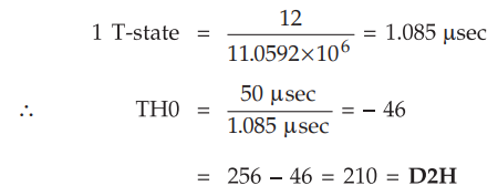
For
square wave TON = T/2 = 50 µsec
#include
<reg51.h>
sbit
SW = P1^2;
sbit
ST = P2^1;
sbit
SWAVE =P2^3;
void
timer 0 (void) interrupt 1
{
swave
= ~ swave ; /* toggle pin */
}
void
serial 0() interrupt 4
{
if
(TI = = 1)
{
SBUF
= '*'; /*send '*' to serial port*/
TI
= 0; /* clear interrupt */
}
else
{
RI
= 0; /* clear interrupt */
}
}
void
main ()
{
SW
= 1; /* Make switch input */
TH1
= - 6; /* 4800 baud rate */
TMOD
= 0X22; /* Mode 2 for both timers */
TH0
= 0XD2; /* Load count D2H for timer 0 */
SCON
= 0X50; /* 8-bit data, 1-stop bit */
TR0
= 1; /* start timer 0 */
TR1
= 1; /* start timer 1 */
IE
= 0X92; /* Enable interrupt for T0 */
While
(1) /* wait for interrupt */
{
ST
= SW; /* send status of SW to pin P2.1 */
}
}
Review Questions
1. Discuss the serial
interface of 8051. AU : May-05, Marks 8
2. Discuss in detail,
the hardware and software support provided by 8051 for serial communication. AU : Dec.-09,17, Marks
16
3. Describe how the
serial communication is performed in 8051. AU : May-10, Dec.-08,11, Marks 8
4. Draw the
flowchart for programming of serial port of 8051. AU : Dec.-11, Marks 2
5. Explain the
different serial communication modes in 8051. AU : June-07, Marks 8
6. Write 8051 ALP to transmit "Hello World" to PC at 9600 baud for external crystal frequency of AU : June-07, Marks 8
Microprocessors and Microcontrollers: Unit III: (c) 8051 I/O Ports, Timer, Serial Port & Interrupts : Tag: : - 8051 Serial Port