Microprocessors and Microcontrollers: Unit III: (c) 8051 I/O Ports, Timer, Serial Port & Interrupts
8051 Timer Modes and Programming
There are four modes of timer, mode 0, mode 1, mode 2 and mode 3. All these modes and their programming are discussed in this section. Mode 1 and mode 2 are widely used, so we will discuss them in detail.
8051 Timer Modes and Programming
AU
: Dec.-07,11,15, May-10,11,14,17
There
are four modes of timer, mode 0, mode 1, mode 2 and mode 3. All these modes and
their programming are discussed in this section. Mode 1 and mode 2 are widely
used, so we will discuss them in detail.
Mode
0 :
Both Timers in Mode 0 are 8-bit Counters with a divide-by-32 prescaler. This
13-bit timer is MCS-48 compatible. Fig. 16.4.1 shows the Mode 0 operation as it
applies to Timer 1. In this mode, the Timer register is configured as a 13-bit
register. As the count rolls over from all Is to all Os, it sets the Timer
interrupt flag TF1. The counted input is enabled to the Timer when TRI = 1 and
either GATE = 0 or ![]() = 1. (Setting GATE = 1 allows the Timer to be
controlled by external input
= 1. (Setting GATE = 1 allows the Timer to be
controlled by external input ![]() , to facilitate pulse width measurements.)
TRI is a control bit in the Special Function Register TCON GATE is in TMOD.
, to facilitate pulse width measurements.)
TRI is a control bit in the Special Function Register TCON GATE is in TMOD.

The
13-bit register consists of all 8 bits of TH1 and the lower 5 bits of TL1. The
upper 3 bits of TL1 are indeterminate and should be ignored. Setting the run
flag (TRI) does not clear the registers.
Mode
0 operation is the same for Timer 0 as for Timer 1. Substitute TRO, TFO and ![]() for the corresponding Timer 1 signals in Fig. 16.4.1. There are two
different GATE bits, one for Timer 1 (TMOD.7) and one for Timer 0 (TMOD.3).
for the corresponding Timer 1 signals in Fig. 16.4.1. There are two
different GATE bits, one for Timer 1 (TMOD.7) and one for Timer 0 (TMOD.3).
Mode
1 :
Both Timers in Mode 1 are 16-bit Counters As the count rolls over from all Is
to all Os, it sets the Timer interrupt flag TF. The counted input is enabled to
the Timer when TR = 1 and either GATE = 0 or ![]() = 1. (Setting GATE = 1
allows the Timer to be controlled by external input
= 1. (Setting GATE = 1
allows the Timer to be controlled by external input ![]() , to facilitate pulse
width measurements.)
, to facilitate pulse
width measurements.)
Timer
0 Mode 1 Programming : The Fig. 16.4.2 shows the timer control logic for timer
0 in mode 1.
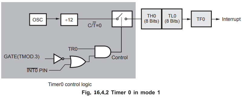
A
time delay can be generated using mode 1 of the timer 0 using following steps :
1.
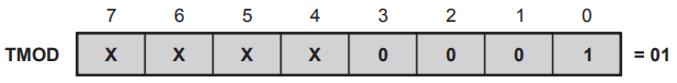
Load TMOD register indicating timer 0 is used and mode 1 is selected.
2.
Load TL0 and TH0 registers with count values.
3.
Start the timer by setting TR0 bit = 1.
4.
Monitor the timer flag (TF0) with the JNB TF0, target address instruction. When
it is raised, get out of the loop.
5.
Stop the timer by clearing TRO bit = 0 with CLR TR0 instruction.
6.
Clear TFO flag with CLR TFO instruction.
When
start and stop of timer is done using software, no external hardware is needed
for the same. This is illustrated in the Fig. 16.4.3.

Timer
1 Mode 1 Programming : The Fig. 16.4.4 shows the timer control logic for timer
1 in mode 1.
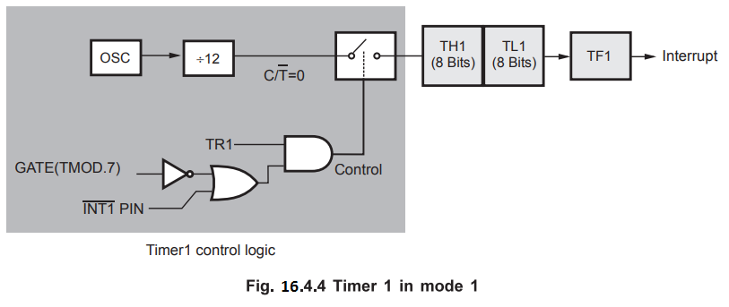
A
time delay can be generated using mode 1 of the timer 1 using following steps :
1.
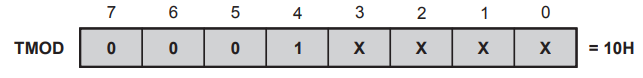
Load TMOD register indicating timer 1 is used and mode 1 is selected.
2.
Load TL1 and TH1 registers with count values.
3.
Start the timer by setting TR1 bit = 1.
4.
Monitor the timer flag (TF1) with the JNB TF1, target address instruction. When
it is raised, get out of the loop.
5.
Stop the timer by clearing TR1 bit = 0 with CLR TRI instruction.
6.
Clear TF1 flag with CLR TF1 instruction.
When
start and stop of timer is done using software, no external hardware is needed
for the same. It is illustrated in the Fig. 16.4.5.

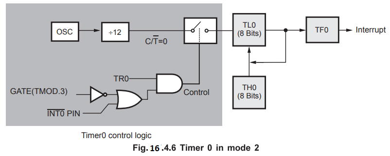
Mode
2 :
Mode 2 configures the Timer register as an 8-bit Counter (TL) with automatic
reload, as shown in Fig. 17.4.6. Overflow from TL only sets TF, but also
reloads TL with the contents of TH, which is preset by software. The reload
leaves TH unchanged.
Timer 0 Mode 2 Programming : The Fig. 16.4.6 shows the timer control logic for timer 0 in mode 2.
A
time delay can be generated using mode 2 of the timer 0 using following steps :
1.
Load TMOD register indicating timer 0 is used and mode 2 is selected.

2.
Load TH0 register with count value.
3.
Start the timer by setting TR0 bit = 1.
4.
Monitor the timer flag (TF0) with the JNB TF0, target address instruction. When
it is raised, get out of the loop.
5.
Clear the TF0 flag, with CLR TF0 instruction.
6.
Go back to step 4. There is no need to load TH0 register again since Mode 2 is
auto-reload.
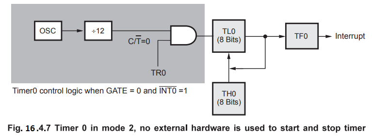
When
start and stop of timer is done using software, no external hardware is needed
for the same. It is illustrated in the Fig. 16.4.7.
Timer
1 Mode 2 Programming : The Fig. 16.4.8 shows the timer control logic for timer
1 in mode 2.

A
time delay can be generated using mode 2 of the timer 1 using following steps :
1.
Load TMOD register indicating timer 1 is used and mode 2 is selected.

2.
Load TH1 register with count value.
3.
Start the timer by setting TR1 bit = 1.
4.
Monitor the timer flag (TF1) with the JNB TF1, target address instruction. When
it is raised, get out of the loop.
5.
Clear the TF1 flag, with CLR TF1 instruction.
6.
Go back to step 4. There is no need to load TH1 register again since Mode 2 is
auto-reload.
When
start and stop of timer is done using software, no external hardware is needed
for the same. It is illustrated in the Fig. 16.4.9.

Mode
3 :
Timer 1 in Mode 3 simply holds its count. The effect is the same as setting TRI
= 0. Timer 0 in Mode 3 establishes TL0 and TH0 as two separate counters. The
logic for Mode 3 on Timer 0 is shown in Fig. 16.4.10. TL0 uses the Timer 0
control bits :![]() GATE, TR0,
GATE, TR0, ![]() , and TF0. TH0 is locked into a
timer mode (counting machine cycles) and takes over the use of TRI and TF1 from
Timer 1. Thus, TH0 now controls the : Timer 1 interrupt.
, and TF0. TH0 is locked into a
timer mode (counting machine cycles) and takes over the use of TRI and TF1 from
Timer 1. Thus, TH0 now controls the : Timer 1 interrupt.

The
Table 16.4.1 summarizes the modes of timers.

Review Question
1. Describe the
different modes of operation of timers in 8051.
AU : Dec.-07,11, May-10,11,14,17,
Marks 16
2. Explain the Timers
of 8051 microcontroller with appropriate diagrams.
AU : Dec.-15, Marks 16
Microprocessors and Microcontrollers: Unit III: (c) 8051 I/O Ports, Timer, Serial Port & Interrupts : Tag: : - 8051 Timer Modes and Programming