Microprocessors and Microcontrollers: Unit III: (c) 8051 I/O Ports, Timer, Serial Port & Interrupts
8051 Timers
8051 has two timers, timer 0 and timer 1. Basically both, timer 0 and timer 1 are 16-bit registers.
8051 Timers
AU
: May-08, Dec.-09, 11, 13
8051
has two timers, timer 0 and timer 1. Basically both, timer 0 and timer 1 are
16-bit registers. Since 8051 is an 8-bit microcontroller, each 16-bit register
can be accessed as low-byte register(TL) and high-byte register(TH). Fig. 16.3.1
shows the timer 0 and timer 1 registers. These registers can be accessed like
other registers (A, B, R0, R1 etc.) in 8051.

1. Structure of TMOD Register
Timer/counter
mode control (TMOD) is the special function register in 8051 having format as
shown in Fig. 16.3.2.
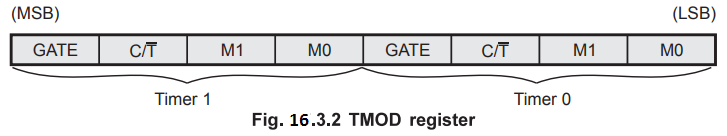
The
TMOD register is responsible for configuring the timers for the following
operations :
■
Select Timer 0 to operate as a counter or timer
■
Select Timer 1 to operate as a counter or timer
■
Select the mode in which timer should operate.
M1,
M0 : These bits select the timer mode. There are four different modes of timer,
mode 0, mode 1, mode 2 and mode 3. All these modes are discussed in the further
section.

 This bit is cleared (C/
![]() = 0) for selecting 'timer' operation and is
set (C/
= 0) for selecting 'timer' operation and is
set (C/![]() = 1) for selecting 'counter' operation.
= 1) for selecting 'counter' operation.
GATE
:
Gating control when set. Timer/Counter "x" is enabled only while
"INTx" pin is high and "TRx" control bit is set. When
cleared Timer "x" is enabled whenever "TRx" control bit is
set.
2. Structure of TCON Register
The
Fig. 16.3.3 shows the format for the TCON register of 8051.
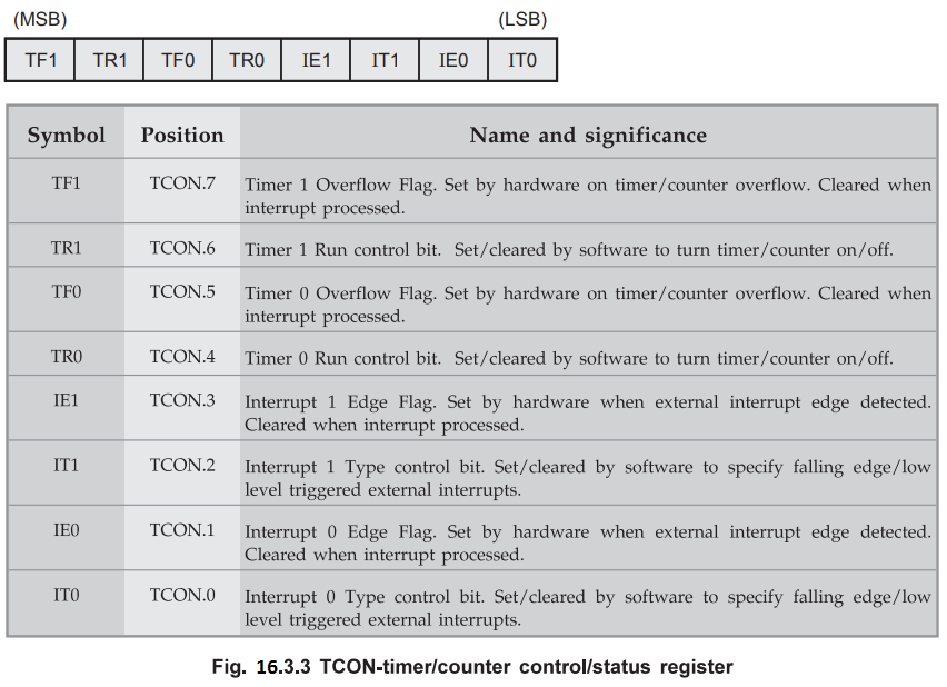
The
TCON register controls the following timer operations :
•
Start and stop timer 0 and timer 1
•
Provides status of timer/counter overflows
•
Provides status of external interrupts
•
Configures external interrupts as either low level triggered or falling edge
triggered.
Example
16.3.1 Indicate the effect of following 8051
instructions.
a.
MOV TMOD, #00010000B b. MOV TMOD, #00000001B c. MOV TMOD, #04
Solution
:
a.
MOV TMOD, #00010000B : The effect of this instruction is
to set Timer 1 in mode 1 and Gate = 0 for internal clocking.
b.
MOV TMOD, #00000001B : The effect of this instruction is
to set Timer 0 in mode
1
and Gate = 0 for internal clocking.
c.
MOV TMOD, #04 : The effect of this instruction is to
select timer 0 to run in the counter mode.
Example
16.3.2 Perform the following operations using bit
addressable instructions
Solution
:
a) SETB TRI ; starts timer 1 by setting TCON.6 = 1
b)
CLR TRO ; stops timer 0 by clearing TCON.4 = 0
Review Questions
1. Explain the
timer/counter functional unit of microcontroller 8051 with relevant diagrams. AU : May-08, Marks 16
2. Discuss in detail
the on chip timers supported by 8051, bringing out the various modes of operation
of these timers. AU : Dec.-09, Marks 16
3. Draw the TMOD
register format and explain. AU : Dec.-11, Marks 4
4. Discuss about the timers in 8051 with suitable examples. AU : Dec.-13, Marks 16
Microprocessors and Microcontrollers: Unit III: (c) 8051 I/O Ports, Timer, Serial Port & Interrupts : Tag: : - 8051 Timers