Microprocessors and Microcontrollers: Unit I: (b) 8085 Interrupts
8085 Interrupt Structure and Operation
Types - Overall Structure - Masking / Unmasking - Pending Interrupts
Questions : 1. Explain the 8085 interrupts system in detail. 3. With necessary diagrams, write short note on interrupt structure of 8085. 3. Discuss the interrupts of 8085. 4. Describe the interrupts of 8085 microprocessor. 5. Define vector address. List the various interrupts of 8085 processor and elucidate the use of interrupt service routine.
8085 Interrupt Structure and Operation
AU
: May-04, 07, 08, 09, 10, 12, 14, 16, 17, 18, Dec.-09, 11, 12, 13, 15, 18
1. Types of Interrupts
The
8085 has multilevel interrupt system. It supports two types of interrupts : a.
Hardware b. Software
Hardware
:
Some pins on the 8085 allow peripheral device to interrupt the main program for
I/O operations. When an interrupt occurs, the 8085 completes the instruction it
is currently executing and transfers the program control to a subroutine that
services the peripheral device. Upon completion of the service routine, the MPU
returns to the main program. These types of interrupts, where MPU pins are used
to receive interrupt requests, are called hardware interrupts.
Software
:
In software interrupts, the cause of the interrupt is an execution of the
instruction. These are special instructions supported by the microprocessor.
After execution of these instructions microprocessor completes the execution of
the instruction it is currently executing and transfers the program control to
the subroutine program. Upon completion of the execution of the subroutine
program, program control returns to the main program.
2. Overall Interrupt Structure
a.
Hardware Interrupts in 8085
The
8085 has five hardware interrupts :
1.
TRAP 2. RST 7.5 3. RST 6.5
4. RST 5.5 5. INTR
When
any of these pins, except INTR, is active, the internal control circuit of the
8085 produces a CALL to a predetermined memory location. This memory location,
where the subroutine starts is referred to as vector location or vector address
and such interrupts are called vectored interrupts. The INTR is not a vectored
interrupt. It receives the address of the subroutine from the external device.
The
Fig. 4.2.1 shows the interrupt structure of 8085. The figure indicates that,
the 8085 is designed to respond to edge triggering, level triggering or both.
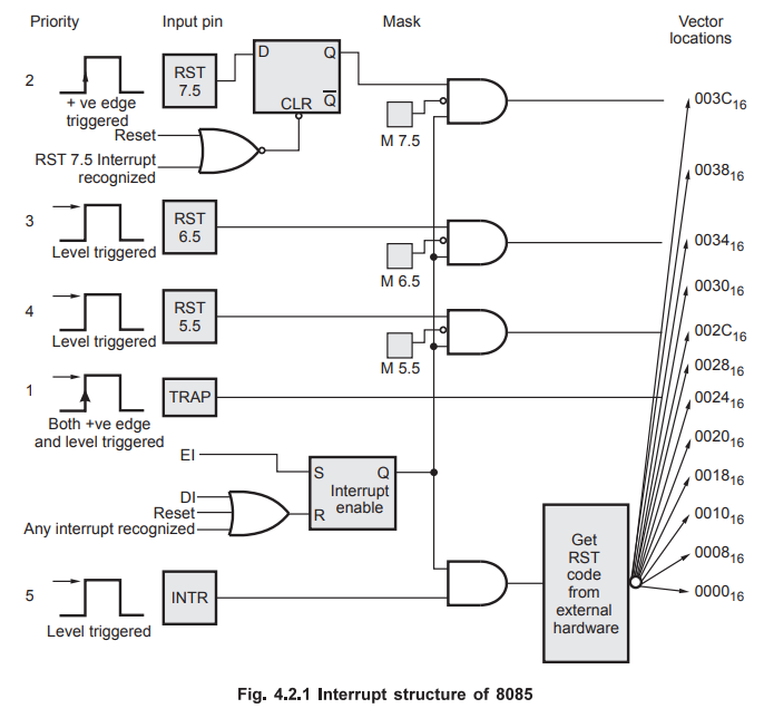
TRAP
:
This interrupt is a non-maskable interrupt. It is unaffected by any mask or
interrupt enable. TRAP has the highest priority. TRAP interrupt is edge and
level triggered. This means that the TRAP must go high and remain high until it
is acknowledged. This avoids false triggering caused by noise and transients.
Once
the TRAP is acknowledged, the 8085 completes its current instruction. It then
pushes the address of the next instruction i.e. return address onto the stack
and loads PC with the fixed vector address 0024H. Due to this, 8085 starts
execution of instructions from address 0024H which is the starting address of
an interrupt service routine for TRAP.
RST
7.5 : The RST 7.5 interrupt is a maskable interrupt. It
has the second highest priority. As shown in Fig. 4.2.1, it is positive edge
triggered and the positive edge trigger is stored internally by the D flip-flop
until it is cleared by software reset using SIM instruction or by internally
generated ACKNOWLEDGE signal.
The
positive edge signal on the RST 7.5 pin sets the D flip-flop. If the mask bit M
7.5 is 0 i.e. RST 7.5 is unmasked then 8085 completes its current instruction.
It then pushes the address of the next instruction onto the stack and loads PC
with the fixed vector address 003CH. Due to this, 8085 starts execution of
instructions from address 003CH which is the starting address of an interrupt
service routine for RST 7.5.
RST
6.5 and RST 5.5 : The RST 6.5 and RST 5.5 both are level
triggered. These interrupts can be masked using SIM instruction. The RST 6.5
has the third priority whereas RST 5.5 has the fourth priority. The vector
addresses of RST 6.5 and RST 5.5 are 0034H and 002CH respectively. After
recognition of RST 6.5 or RST 5.5 interrupt, 8085 completes its current
instruction; pushes the address of next instruction onto the stack and loads PC
with corresponding vector address.
INTR
: INTR
is a maskable interrupt, but not the vector interrupt. It has the lowest
priority. The following sequence of events occur when INTR signal goes high.
1.
The 8085 checks the status of INTR signal during execution of each instruction.
2.
If INTR signal is high, then 8085 completes its current instruction and sends
an active low interrupt acknowledge signal  if the interrupt is
enabled.
if the interrupt is
enabled.
3.
In response to the  signal, external logic places an instruction OPCODE
on the data bus. In the case of multibyte instruction, additional interrupt
acknowledge machine cycles are generated by the 8085 to transfer the additional
bytes into the microprocessor.
signal, external logic places an instruction OPCODE
on the data bus. In the case of multibyte instruction, additional interrupt
acknowledge machine cycles are generated by the 8085 to transfer the additional
bytes into the microprocessor.
4.
On receiving the instruction, the 8085 saves the address of next instruction on
stack and executes received instruction.
Note
:
Theoretically, the external logic can place any instruction code on the data
bus in response to the . However, only CALL and RST codes save the
contents of the PC on the stack and branch program control to the subroutine
address.
Response
for RST instruction : If the external device places an opcode
for any one of the RST instruction (RST 0 - RST 7), then 8085 pushes the
contents of PC onto the stack. It then branches the program control to the
vector address of the corresponding RST instruction.
Response
for CALL instruction : If the external device places an
opcode for CALL instruction then 8085 generates two additional interrupt
acknowledge cycles.
1.
It sends an active low interrupt acknowledge signal second time.
2.
In response to second signal, external logic places the lower byte
address for the CALL instruction.
3.
After receiving lower byte address, 8085 sends the third interrupt acknowledge
signal.
4.
In response to third signal, external logic places the higher byte
address for the CALL instruction.
5.
After receiving sixteen bit address for CALL, 8085 pushes the contents of the
PC onto the stack and branches the program control to the subroutine whose
address is received from the external logic.
Table
4.2.1 shows the summary of hardware interrupts in 8085.

b.
Software Interrupts in 8085
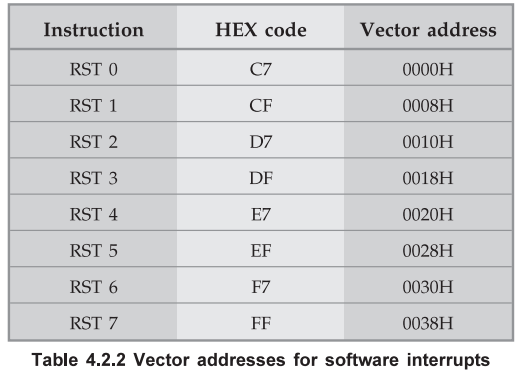
The
8085 has eight software interrupts from RST 0 to RST 7. The vector address for
these interrupts can be calculated as follows :
Interrupt
number × 8 = Vector address
For
example :
5
× 8 = 40 = 28H
.'.
Vector address for interrupt RST 5 is 0028H.
The
Table 4.2.2 shows the vector addresses of all interrupts.
3. Masking / Unmasking of Interrupts
As
mentioned earlier, maskable interrupts are enabled and disabled under program
control. In this section we will see how interrupts can be masked or unmasked
using program control. There are four instructions used for control of
interrupts :
1.
EI 2. DI 3. RIM
4. SIM
EI
: Enable Interrupt
The
EI instruction sets the interrupt enable flip-flop, as shown in Fig. 4.2.1.
Thus RST 7.5, RST 6.5, RST 5.5 and INTR are enabled using EI instruction.
It
is important to note that when any interrupt is acknowledged, interrupt enable
flip-flop resets and disables all interrupts. To enable interrupt in further
process it is necessary to execute EI instruction within interrupt service
routine.
DI
: Disable Interrupt
The
DI instruction resets the interrupt enable flip-flop, as shown in Fig. 4.2.1.
Thus it disables RST 7.5, RST 6.5, RST 5.5 and INTR interrupts.
SIM
: Set Interrupt Mask
This
instruction is used to set interrupt mask and to send serial output. It
transfers the contents of accumulator to interrupt control logic and serial I/O
port. Thus it is necessary to load appropriate contents in the accumulator
before execution of SIM instruction.
4. Pending Interrupts
The
Read Interrupt Mask, RIM, instruction loads the status of the interrupt mask,
the pending interrupts and the contents of the serial input data line, SID,
into the accumulator. Thus, it is possible to monitor status of interrupt mask,
pending interrupts and serial input. There are number of interrupts. When one
interrupt is being serviced, other interrupt requests may occur. If the
interrupt requests are of higher priority, 8085 branches program control to the
requested interrupt service routines. But when the interrupt requests are of
lower priority, 8085 stores the information about these interrupt requests.
Such interrupts are called pending interrupts. The status of pending interrupts
can be monitored using RIM instruction.
Example
4.2.1 Write an 8085 assembly language program by assuming
that microprocessor is completing an RST 7.5 interrupt request; check to
see if RST 6.5 is pending. If it is pending, enable RST 6.5 without
affecting any other interrupts; otherwise return to the main program.
AU
: Dec.-12, Marks 8
Solution
:
RIM
; Read the status of pending interrupts using RIM instruction
MOV
B, A ; Save the status in register B
ANI
20H ; Check whether RST 6.5 is pending
RZ
; If RST 6.5 is not pending return to main program
MOV
A, B ; Get interrupt status in A register
ANI
FDH ; Set DI = 0 to enable RST 6.5
ORI
08H; Set D3 = 1, for enabling interrupt enable flag
EI
; Set interrupt enable flip-flop
RET
; Return to main program
Review Questions
1. Explain the 8085
interrupts system in detail.
AU : May-04, Marks 10
2. Write short notes
on vectored interrupts of 8085.
AU : May-07, Marks 8
3. With necessary
diagrams, write short note on interrupt structure of 8085.
AU : May-08, 10,
Dec.-11, Marks 6
4. Explain the
interrupt structure of 8085 microprocessor.
AU : Dec.-13,15,17,
May-14,17, Marks 16
5. Discuss the
interrupts of 8085.
AU : Dec-09, May-12,
Marks 10
6. What is TRAP
interrupt and its significance ?
AU : May-12, Marks 2
7. Describe the
interrupts of 8085 microprocessor.
AU : May-16, Marks 8
8. Describe the
interrupts of 8085 and its types with service routine.
AU : May-18, Marks 7
9. Define vector
address. List the various interrupts of 8085 processor and elucidate the use of
interrupt service routine.
AU : Dec.-18, Marks 13
Microprocessors and Microcontrollers: Unit I: (b) 8085 Interrupts : Tag: : Types - Overall Structure - Masking / Unmasking - Pending Interrupts - 8085 Interrupt Structure and Operation
Related Topics
Related Subjects
Microprocessor and Microcontroller
EE3404 MCU 4th Semester EEE Dept | 2021 Regulation | 4th Semester EEE Dept 2021 Regulation