Microprocessors and Microcontrollers: Unit IV: (a) Programmable Peripheral Interface (PPI) - 8255
8255 Programming and Operation
Microprocessors and Microcontrollers
1. Programming in Mode 0 2. Programming in Mode 1 (Input / Output with Handshake) 3. Programming in Mode 2 (Strobes Bi-directional Bus I/O)
8255 Programming and Operation
1. Programming in Mode 0
The
Ports A, B and C can be configured as simple input or output ports by writing
the appropriate control word in the control word register.
2. Programming in Mode 1 (Input / Output with Handshake)
Both
Group A and Group B can operate in Mode 1, either together, or individually,
with each port containing an 8-bit latched Input or Output data port, and a
4-bit port which is used for control and status of the 8-bit port.
When
Port A is to be programmed as an input port, PC3 , PC4
and PC5 are used for control. PC6 and PC7 are
not used and can be Input or Output, as programmed by bit D3 of the
control word. When Port A is programmed as an output port, PC3 , PC6
and PC7 are used for control and PC4 and PC5
can be Input or Output, as programmed by bit D3, of the control
word.
When
Port B is to be programmed as an input or output port, PC0, PC1
and PC2 are used for control.
Mode
1 : Input control signals
1. ![]() (Strobe Input) : This is an active low input signal
for 8255 and output signal for the input device. The input device activates
this signal to indicate CPU that the data to be read is already sent on the
port lines of 8255 port. Upon activation of this signal 8255 loads the data
from the input port lines into the input buffer of that port.
(Strobe Input) : This is an active low input signal
for 8255 and output signal for the input device. The input device activates
this signal to indicate CPU that the data to be read is already sent on the
port lines of 8255 port. Upon activation of this signal 8255 loads the data
from the input port lines into the input buffer of that port.
2.
IBF (Input Buffer Full) : This is an active high output
signal for 8255 and an input signal for input device. This signal is generated
by 8255 in response to ![]() signal as an acknowledgment to input device.
It also indicates to the input device that the input buffer is full and it is
not ready to accept next byte from the input device. Therefore input device
sends data on the port lines only when IBF signal is not active. The IBF signal
is deactivated when CPU reads the data from input buffer of the respective port
by activation of
signal as an acknowledgment to input device.
It also indicates to the input device that the input buffer is full and it is
not ready to accept next byte from the input device. Therefore input device
sends data on the port lines only when IBF signal is not active. The IBF signal
is deactivated when CPU reads the data from input buffer of the respective port
by activation of ![]() signal.
signal.
3.
INTR (Interrupt Request) : This is an active high output
signal generated by 8255. A 'high' on this output can be used to interrupt the
CPU when an input device is requesting service. The 8255 sets the INTR when ![]() signal is 'one', IBF signal is 'one' and INTE is 'one', indicating CPU that the
data from the input device is available in the input buffer. This signal is
reset by the falling edge of the
signal is 'one', IBF signal is 'one' and INTE is 'one', indicating CPU that the
data from the input device is available in the input buffer. This signal is
reset by the falling edge of the ![]() signal i.e. immediately after
reading the data from the input buffer.
signal i.e. immediately after
reading the data from the input buffer.
INTE
(Interrupt Enable) flip flop is used to enable or disable INTR (Interrupt
request) signal. If INTE flip-flop is set, the interrupt request is generated
depending on the status of ![]() and IBF signals. If INTE flip flop is
reset, the interrupt request is not generated, allowing masking facility for
the interrupt.
and IBF signals. If INTE flip flop is
reset, the interrupt request is not generated, allowing masking facility for
the interrupt.
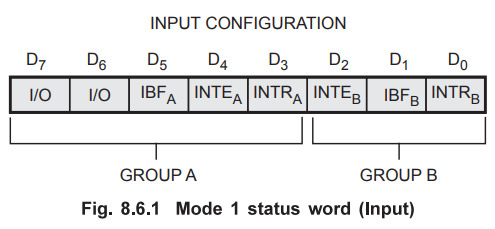
Mode
1 : Status Word (Input)
If
the CPU is busy with other system operations, it can read data from the input
port when it is interrupted. This is often called Interrupt driven I/O.
However, if the CPU is otherwise not busy with other jobs, it can continuously
poll (read) the status word to check for an IBFA. This is often
called Program Controlled I/O. The status word is accessed by reading Port C (A1
A0 must be 10,  must be
low). The status word format when Ports A and B are input ports in Mode 1, is
shown in Fig. 8.6.1.
must be
low). The status word format when Ports A and B are input ports in Mode 1, is
shown in Fig. 8.6.1.
Mode
1 : Output control signals
1. ![]() (Output Buffer Full) : This is an active low output signal for 8255
and input signal for the output device. The 8255 activates this signal to
indicate output device that data is available on the output port. Upon
activation of
(Output Buffer Full) : This is an active low output signal for 8255
and input signal for the output device. The 8255 activates this signal to
indicate output device that data is available on the output port. Upon
activation of ![]() signal, output device reads data from the output port and
acknowledges it by
signal, output device reads data from the output port and
acknowledges it by ![]() signal. The
signal. The ![]() signal is activated at the rising edge of the
signal is activated at the rising edge of the ![]() signal and de-activated at the falling edge f the
signal and de-activated at the falling edge f the ![]() signal.
signal.
2. ![]() (Acknowledge Input) : This is an active low
input signal for 8255 and output signal for the output device. The output device
generates this signal to indicate 8255 that the data from port A or Port B has
been accepted.
(Acknowledge Input) : This is an active low
input signal for 8255 and output signal for the output device. The output device
generates this signal to indicate 8255 that the data from port A or Port B has
been accepted.
3.
INTR (Interrupt Request) : This is an active high output
signal generated by 8255. A 'high' on this output can be used to interrupt the
CPU when an output device has accepted data transmitted by the CPU. The 8255
sets the INTR when ![]() signal is 'one',
signal is 'one', ![]() is 'one' and INTE is
'one', indicating that the output device is ready to accept next data byte.
This signal is reset by the falling edge of the
is 'one' and INTE is
'one', indicating that the output device is ready to accept next data byte.
This signal is reset by the falling edge of the ![]() signal i.e.
immediately after sending the data to the output port.
signal i.e.
immediately after sending the data to the output port.
INTE
(Interrupt Enable) flip flop is used to enable or disable INTR (Interrupt
Request) signal. If INTE flip flop is set, the interrupt request is generated
depending on the status of  signals. If INTE flip flop is reset, the
interrupt request is not generated, allowing masking facility for the
interrupt.
signals. If INTE flip flop is reset, the
interrupt request is not generated, allowing masking facility for the
interrupt.
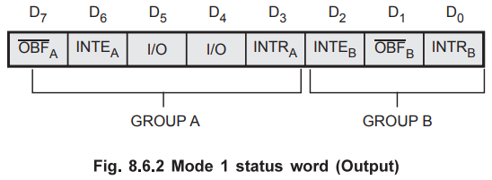
Mode
1 : Status Word (Output)
The
status word is accessed by issuing a Read to Port C. The format of the status
word when Ports A and B are Output ports in Mode 1 is shown in Fig. 8.6.2.
3. Programming in Mode 2 (Strobes Bi-directional Bus I/O)
When
the 8255 is operated in Mode 2 (by loading the appropriate control word), Port
A can be used as a bi-directional 8-bit 1/O bus using for handshaking. Port B
can be programmed in Mode 0 or in Mode 1. When Port B is programmed in mode 1,
PC0 - PC2 lines of Port C are used as handshaking
signals.
Mode
2 : Control signals
INTR
(Interrupt Request) : A 'high' on this output can be used to
interrupt the CPU for input or output operations.
Output
Control Signals
 This is an active low output which indicates
that the CPU has written data into Port A.
This is an active low output which indicates
that the CPU has written data into Port A.
 This is an active low input signal (generated by the peripheral) which enables
the tri-state output buffer of Port A and makes Port A data available to the
peripheral. In Mode 2, Port A outputs are in tri-state until enabled.
This is an active low input signal (generated by the peripheral) which enables
the tri-state output buffer of Port A and makes Port A data available to the
peripheral. In Mode 2, Port A outputs are in tri-state until enabled.
INTE
1 :
This is the flip-flop associated with Output Buffer Full. INTE 1 can be used to
enable or disable the interrupt by setting or resetting PC6 in the
BSR Mode.
Input
Control Signals
 This is an active low input signal which
enables Port A to latch the data available at its input.
This is an active low input signal which
enables Port A to latch the data available at its input.
IBF
(Input Buffer Full Flip-Flop) : This is an active high
output which indicates that data has been loaded into the input latch of Port
A.
INTE
2 :
This is an Interrupt enable flip-flop associated with Input Buffer Full. It can
be controlled by setting or resetting PC4 in the BSR Mode.
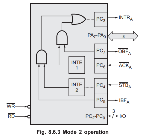
Mode
2 : Port A operation
Fig.
8.6.3 shows Port A and associated control signals when 8255 is in Mode 2.
Interrupts are generated for both output and input operations on the same INTRA
(PC3) line.
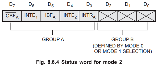
Status
Word In Mode 2
The
status word for Mode 2 (accessed by reading Port C) is shown in Fig. 8.6.4. D7
-D3 of the status word carry information about  . The
status of the bits D2 - D0 depends on the mode setting of
Group B. If B is programmed in Mode 0, D2 – D0 are the
same as PC2 – PC0 (Simple I/O), however if B is in Mode
1, D2 – D0 carry
information about the control signals for Port B, depending upon whether Port B
is an Input port or Output port respectively.
. The
status of the bits D2 - D0 depends on the mode setting of
Group B. If B is programmed in Mode 0, D2 – D0 are the
same as PC2 – PC0 (Simple I/O), however if B is in Mode
1, D2 – D0 carry
information about the control signals for Port B, depending upon whether Port B
is an Input port or Output port respectively.
Review Questions
1. Explain the mode
1 input mode operation of 8255 in detail.
2. With neat block
diagram, explain the operating modes of 8255 PPI.
AU May-04, Marks 8
AU May-11, Marks 8
3. Explain the
operation of 8255 PPI Port A programmed as input and output in mode 1 with
necessary handshaking signals.
AU May-11, Marks 8
4. Explain in
detail, the operating modes of 8255 PPI with control registers.
AU : Dec.-12, Marks
8
Microprocessors and Microcontrollers: Unit IV: (a) Programmable Peripheral Interface (PPI) - 8255 : Tag: : Microprocessors and Microcontrollers - 8255 Programming and Operation