Linear Integrated Circuits: Unit II: Characteristics of Op-amp
A.C. Characteristics of Op-amp
The important a.c. characteristics of op-amp are, 1. Slew rate 2. Frequency response
A.C. Characteristics of Op-amp
The
important a.c. characteristics of op-amp are,
1.
Slew rate 2. Frequency response
The
slew rate is already discussed. It indicates the ability of op-amp with which
it can change its output according to changes in the input.
1. Frequency Response of Op-amp
Ideally,
an op-amp should have an infinite bandwidth. This means the gain of op-amp must
remain same for all the frequencies from zero to infinite. Uptill now we have
assumed gain of the op-amp as constant but practically op-amp gain decreases at
higher frequencies. Such a gain reduction with respect to frequency is called
roll off.
This
happens because gain of the op-amp depends on the frequency and hence
mathematically it is a complex number. Its magnitude and the phase angle
changes with the frequency. The plot showing the variations in magnitude and
phase angle of the gain due to the
change in frequency is called frequency response of the op-amp. In such plots,
to accommodate large range of frequency, it is plotted on a logarithmic scale.
The gain magnitude can be plotted as a numerical value or may be expressed in
decibels. When the gain in decibels, phase angle in degrees are plotted against
logarithmic scale of frequency, the plot is called Bode plot. The manner in
which the gain of the op-amp changes with variation in frequency is known as
the magnitude plot and the manner in which the phase shift changes with
variation in frequency is known as the phase angle plot. Generally magnitude
plot is supplied by the manufacturers.
The
dependence of gain of the op-amp on frequency is basically because of presence
of capacitive component in the equivalent circuit of the op-amp. As op-amp uses
BJT and FET, which have the junction capacitances which is very small. But at
high frequency, these offer decreased reactance. Not only the BJT and FET, but
the construction of op-amp also contributes to the presence of capacitance. All
the resistors and transistors in op-amp are fabricated on an insulator.
Similarly there are conducting material wires, connecting the various
components. The two conductors separated by an insulator produces capacitive
effect. Hence overall there exists a capacitive effect in the op-amp.
To
obtain the frequency response, consider the high frequency model of the op-amp
with a capacitor C at the output, taking into account the capacitive effect
present. It is shown in the Fig. 2.15.1.

Let
- jXC be the capacitive reactance due to the capacitor C. From the Fig. 2.15.1,
using voltage divider rule,

Hence
the open loop voltage gain as a function of frequency is

where
AOL (f) = Open loop voltage gain as a function of frequency
AOL
= Gain of op-amp at 0 Hz i.e. d.c.
f
= Operating frequency
fo
= Break frequency or cut off frequency of op-amp
For
a given op-amp and selected value of C, the frequency fo is constant. The
equation (2.15.5) can be written in the polar form as
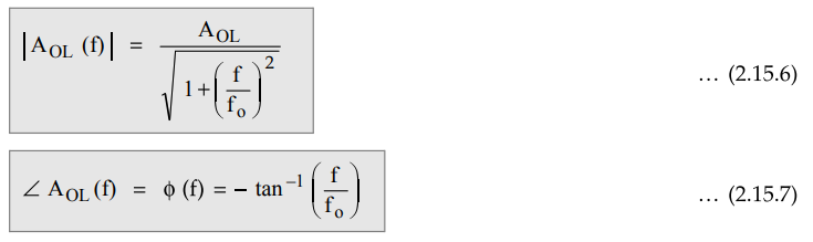
At
f = 0 Hz, the magnitude is AOL , while ϕ (f) = 0°
For
IC 741 op-amp, fo = 5 Hz and the open loop gain 200,000, we can
calculate gain and phase shifts at various frequencies as shown in Table
2.15.1.
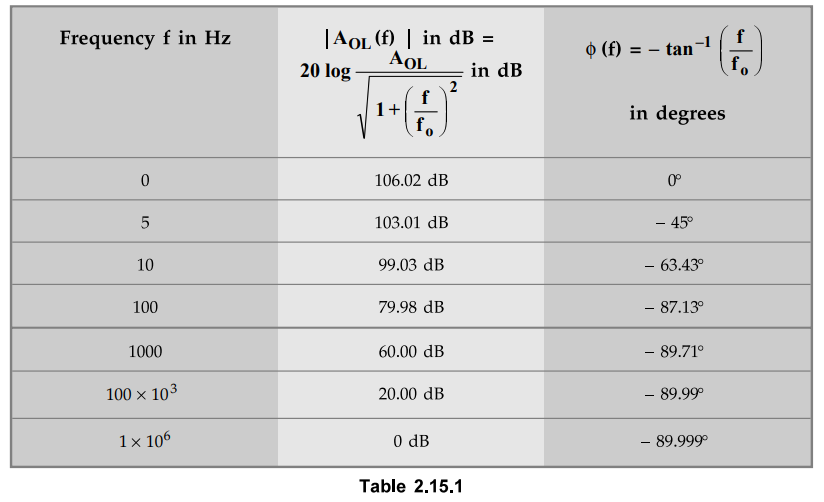
As
the frequency increases till fo, the gain is almost constant but after
fo, the gain reduces with a rate of -20 dB/decade. The maximum
possible phase shift is -90°. Hence the frequency response is shown as in the
Fig. 2.15.2.

The
following observations can be made from the frequency response of an op-amp:
i)
The open loop gain AOL is almost constant from 0 Hz to the break
frequency f 0.
ii)
At f = f0, the gain is 3 dB down from its value at 0 Hz. Hence the frequency f0
is also called as - 3 dB frequency. It is also known as comer frequency.
iii)
After f = f0, the gain AOL(f) decreases at a rate of 20
dB/decadeor6 dB/octave. A decade is 10 times change in frequency while octave
is 2 times change in frequency. As gain decreases, slope of the magnitude plot
is - 20 dB/decade or - 6 dB/octave, after f = fo.
iv)
At a certain frequency, the gain reduces to 0 dB. This means 20 log | AOL(f)|
is 0 dB i.e. | AOL(f) | = 1. Such a frequency is called gain
cross-over frequency or unity gain bandwidth (UGB). It is also called closed
loop bandwidth. UGB is the gain bandwidth product only if an op-amp has a
single break frequency, before AOL(f) dB is zero. IC 741 op-amp has a single
break frequency and its UGB is approximately 1 MHz. So for an op-amp with
single break frequency f0, after fo the gain bandwidth product is constant
equal to UGB.
UGB
= AOLfo … (2.15.8)
UGB
is also called gain bandwidth product and denoted as ft. Thus ft is product of
gain of op-amp and bandwidth.
The
break frequency is nothing but a corner frequency f 0. At this frequency, slope
of the magnitude plot changes. The op-amp for which there is only once change
in the slope of the magnitude plot, is called as single break frequency op-amp.
The IC 741 op-amp, is single break frequency i.e. slope of the plot changes
only once from 0 to -20 dB/decade at f0, as shown in the Fig. 2.15.2.
But
for a single break frequency we can also write
UGB
= Af ff …
(2.15.9)
where Af = Closed loop voltage
gain
ff
= Bandwidth with feedback
So
with feedback, at any point after the break frequency on frequency response,
product of gain and frequency is constant equal to UGB. Remember that this is
applicable only for op-amps with single break frequency like op-amp IC 741.
v)
The phase angle of an op-amp with a single break frequency varies between 0° to
90°. The maximum possible phase shift is - 90°, i.e. output voltage lags input
voltage by 90° when phase shift is maximum.
vi)
At a comer frequency f - fo, the phase shift is - 45°.
For
a typical op-amp, in a data sheet the value of UGB is given instead of the
value of the break frequency fo. Therefore fo can be calculated as
fo
= UGB / AOL … ( 2.15.10)
However,
in a practical op-amp there are number of stages. Each stage introduces a
capacitive component. Thus there are number of different break frequencies. But
op-amp like 741 is internally compensated and has only one break frequency.
Review Questions
1. List the a.c. characteristics of op-amp and define each of
them.
May-07,08,13, Dec.-09, 16, Marks 4
2. Write a technical note on frequency response characteristics
of op-amp.
Dec.-09,10, May-16, Marks 8
Linear Integrated Circuits: Unit II: Characteristics of Op-amp : Tag: : - A.C. Characteristics of Op-amp
Related Topics
Related Subjects

Linear Integrated Circuits
EE3402 Lic Operational Amplifiers 4th Semester EEE Dept | 2021 Regulation | 4th Semester EEE Dept 2021 Regulation