Electrical Machines: Unit II: D.C. Generators
Action of Commutator
DC Generators
It is seen that, the e.m.f. induced in the conductors is always sinusoidal and commutator converts this sinusoidal e.m.f. to unidirectional e.m.f. Let us see, how it happens.
Action of
Commutator
•
It is seen that, the e.m.f. induced in the conductors is always sinusoidal and
commutator converts this sinusoidal e.m.f. to unidirectional e.m.f. Let us see,
how it happens.
•
For simplicity of understanding the commutator action, consider commutator in
its simplest form. Commutator is divided into number of copper segments
insulated from each other. In its mplest form, it is assumed to be divided into
two segments, each is nothing but the half of the entire commutator drum,
separated by insulating material. So in its simplest form it is a ring with two
halves separated by insulation as shown in the Fig. 3.12.1.
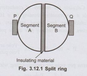
•
Such a ring is called split ring. The brushes P and Q are stationary and
pressed on the surface of split ring. Split ring is mounted on the shaft and
rotates as armature rotates.
•
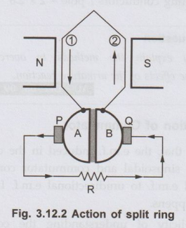
Consider a single turn generator with conductors (1) and (2). These armature
conductors are connected to the two segments of split ring. The external resistance
R is connected across brushes P and Q. Under instant 1, the current flowing
through resistance R is flowing from left to right as shown in the Fig. 3.12.2.
This is by assuming the direction of current through conductor (1) downwards
which is under N pole and through conductor (2) upwards which is under S pole,
at the instant considered. At this instant brush P behaves as positive and
brush Q as negative.
•
After a next half revolution, we have seen that direction of e.m.f. in the
individual conductors reverses. Hence conductor (1) now will carry a current
which will be upwards and due to half revolution
it will be under S pole. Similarly conductor (2) individually will carry a
curren downwards now, and will be under N pole as showr in the Fig. 3.12.3.
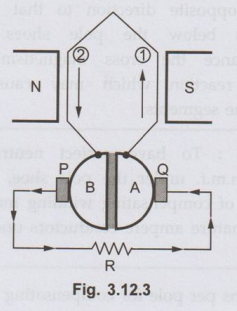
Now
split ring i.e. commutator is mounted on shaft nd rotates with armature. So
when conductors will everse their positions, the split ring sections will also
everse their positions as shown in the Fig. 3.12.3. But rushes P and Q are
stationary and tapping the current from the commutator segments which are in
contact with them.
Hence
under instant 2, segment B will be in contact with brush P ans segment A will
be in contact with brush Q. Due to this current through resitance R maintains
its direction from left to right as shown in the Fig. 3.12.3. Brush P remains positive and Q remains as negative.
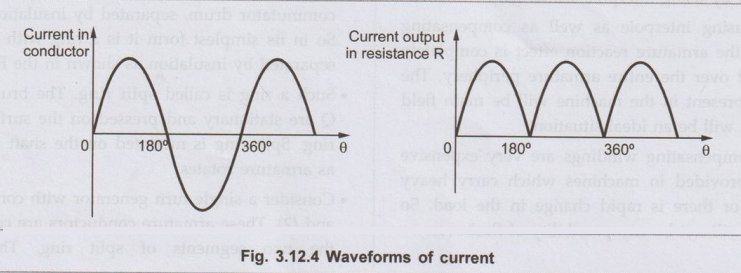
The
Fig. 3.12.4 shows the waveforms of current in the individual conductoor and
current in external resitance R. Effectively inr brush always taps those
conductors carrying current in one particular direction and other brush always
taps those conductors carrying a current which is in 180° opposite direction to
the conductors under brush one. So one brush remains always positive and other
always negative, and the load current is unidirectional.
Key Point:
In the limiting case, number of segments of a commutator is equal to number of
armature coils in a practical generator. Due to this, commutating action is
very fast and almost straight line i.e. pure d.c. can be obtained across the
load.
•
In a practical d.c. generator, the small poles in addition to the main poles,
fixed to the yoke in between the main poles are used to improve the
commutation. These poles are called interpoles.
Review Question
1. Explain the basic
action of commutator.
Electrical Machines: Unit II: D.C. Generators : Tag: : DC Generators - Action of Commutator
Related Topics
Related Subjects

Electrical Machines I
EE3303 EM 1 3rd Semester EEE Dept | 2021 Regulation | 3rd Semester EEE Dept 2021 Regulation