Linear Integrated Circuits: Unit III: Applications of Op-amp
Active Peak Detectors using Op-amp
Working Principle, Pulse, Circuit Diagram | Operational amplifier
In practice number of non-sinusoidal input voltages may exist as the input to the various applications. Such non-sinusoidal waveforms are square, triangular, sawtooth or any other random waveform.
Active Peak Detectors
In
practice number of non-sinusoidal input voltages may exist as the input to the
various applications. Such non-sinusoidal waveforms are square, triangular,
sawtooth or any other random waveform. A conventional a.c. voltmeter cannot be
used to measure the peak of such waveforms as it measures r.m.s. value of
purely sinusoidal waveform. Hence to measure the peak of non-sinusoidal
waveforms a peak detector circuit is used.
A
peak detector is a circuit which notes and remember the peak positive or
negative value of an input signal for an infinite period of time until it is
reset.
Such
a peak detector circuit follows the peaks of an input signal and stores the
highest value, interms of a voltage on a capacitor. If more higher peak occurs
in an input signal, new peak value gets stored, for infinite time until the
capacitor is discharged.
The
Fig. 3.23.1 shows the basic peak detector circuit which explains the basic
principle of such circuit.
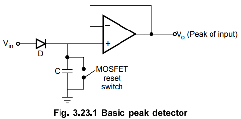
The
circuit is basic positive peak detector. The input signal charges the capacitor
C through diode D. The capacitor gets charged equal to the highest input
voltage, neglecting the small diode drop. The capacitor remains charged to the
peak value of input unless and until discharged with the help of MOSFET reset
switch.
The
op-amp is connected as voltage follower and its output voltage will be equal to
the drop across capacitor which is positive peak of value of the applied
voltage and will remain that way for long periods until next more higher peak
occurs at the input. For negative cycles of input the diode is reverse biased
and the capacitor C retains its voltage.
1. Voltage Follower Peak Detector
More
sophisticated peak detector that buffers the signal source from the capacitor
is shown in the Fig. 3.23.2.

The
op-amp A1 offers a high impedance load to the source. The op-amp A2
acts as a buffer between the capacitor and the load.
With
the same basic principle, the output voltage Vo at any given time is
equal to the voltage on the capacitor, which is nothing but the peak of the
input voltage occurred upto that time.
Whenever
the input signal has more higher peak than the current one, the capacitor
charges upto the new higher input level. But if the input level gets dropped
then the capacitor retains the peak of input voltage as diode D1 gets
reverse biased and diode D2 prevents the output of A1 from going
into the negative saturation. This then serves to improve the recovery time of
A1 when the input attains more positive value. Resistance R2
provides the path for input bias current to A1. The resistance R1
is selected equal to R2 so as to minimize the effect of offset
voltage. To provide the stability against the oscillations, the required
frequency compensation must be provided to the op-amp A1.
The
Fig. 3.23.3 shows the waveforms for the positive peak detector.

The
peak at t1 cannot be recognized as it is less than the previously
occurred peak in the input signal.
The
circuit can be modified to hold the negative peak of a input signal by
reversing the diode connections.
Peak
detectors are used for amplitude modulation in communication and in test and
measurement instrumentation applications.
2. Peak Detector using Integrator
Another
arrangement for the peak detection is to use op-amp A2 as an
integrator. This avoids the necessity to drive a grounded capacitive load.
Because of this, it is easier to maintain the closed loop stability than the
previous circuits. The arrangement is shown in the Fig. 3.23.4.
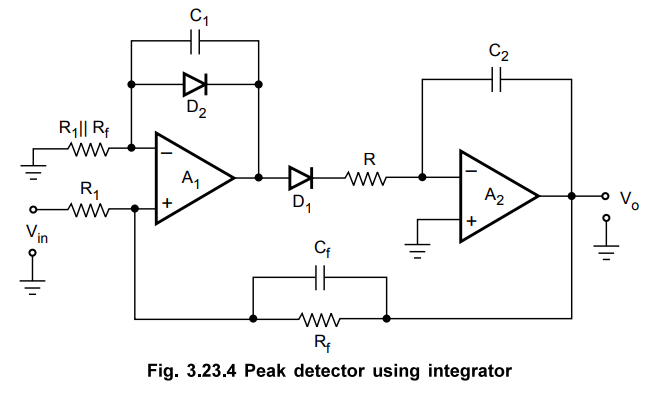
The
capacitors C1 and Cf are required to stabilize the loop.
The circuit detects the positive peak of the input Vin
By
reversing the connections of the diodes D1 and D2, the
same configuration can be used to detect negative peak of the input.
Review Question
1. Explain the working of peak detector using operational
amplifier.
Linear Integrated Circuits: Unit III: Applications of Op-amp : Tag: : Working Principle, Pulse, Circuit Diagram | Operational amplifier - Active Peak Detectors using Op-amp
Related Topics
Related Subjects

Linear Integrated Circuits
EE3402 Lic Operational Amplifiers 4th Semester EEE Dept | 2021 Regulation | 4th Semester EEE Dept 2021 Regulation