Electrical Machines II: UNIT IV: Starting and Speed Control of Three Phase Induction Motor
Adding External Resistance in Rotor Circuit
Three Phase Induction Motor
when the load on the motor is same, motor has to supply same torque as load demands.
Adding External Resistance in Rotor Circuit AU
: May-2000,16,18, Dec -06, 10, 13, 16
For
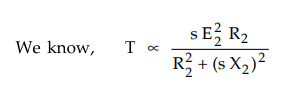
low slip region (sX2) « R2 and can be neglected and for constant supply voltage
E2 is also constant.
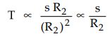
Thus
if the rotor resistance is increased, the torque produced decreases. But when
the load on the motor is same, motor has to supply same torque as load demands.
So motor reacts by increasing its slip to compensate decrease in T due to R2
and maintains the load torque constant. So due to additional rotor resistance R2
, motor slip increases i.e. the speed of the motor decreases. Thus by increasing
the rotor resistance R2 , speeds below normal value can be achieved.
Another advantage of this method is that the starting torque of the motor
increases proportional to rotor resistance.
The
Fig. 7.9.1 shows the torque-speed curves for rotor resistance control.
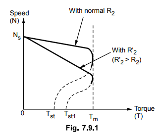
But
this method has following disadvantages :
1.
The large speed changes are not possible. This is because for large speed
change, large resistance is required to be introduced in rotor which causes
large rotor copper loss to reduce the efficiency.
2.
The method can not be used for the squirrel cage induction motors.
3.
The speeds above the normal values can not be obtained.
4.
Large power losses occur due to large I R loss.
5.
Sufficient cooling arrangements are required which make the external rheostats
bulky and expensive.
6.
Due to large power losses, efficiency is low.
Thus
the method is rarely used in the practice.
Example
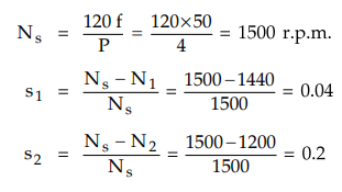
7.9.1 The rotor of a 4-pole, 50 Hz slip ring IM has a
resistance of 0.25 Ω per phase, rotor standstill reactance of 2 Ω and runs at
1440 r.p.m. at full load. Calculate the external resistance per phase which
must be added to lower the speed at 1200 r.p.m., the torque being the same as
before.
Solution
:
P
= 4, f = 50 Hz, R2 = 0.25 Ω, Nj = 1440 r.p.m., N2 = 1200 r.p.m., X2
= 2 Ω
Now
let Rx be the external resistance added so that R2 = Rx
+ R2 for N2 = 1200 r.p.m.
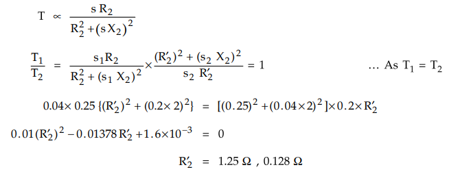
But
R2 cannot be less than R2 hence R2 =1.25 Ω
Rx
= R2 – R2 = 1.25 - 0.25 = 1 Ω
Example
7.9.2 A 4-pole, 3-phase, 50 Hz , slip ring type
induction motor has a rotor resistance of 0.25 Ω per phase and rotor reactance
of 2 Ω per phase at standstill condition. It is running at 1455 r.p.m. speed.
Calculate the value of external resistance per phase required in the rotor
circuit to reduce the speed by 17 %. Assume load torque constant.
Solution
:
P
= 4, f = 50 Hz, R2 = 0.25 Ω, X2 = 2 Ω, N1 = 1455 r.p.m.
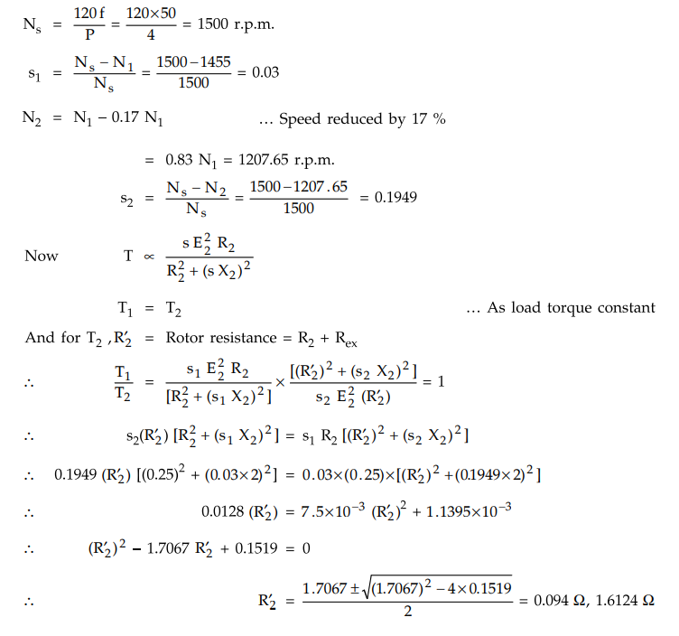
Neglecting
lower value as less than R2.
R2
= R2 + Rex = 1.6124 Ω
Rex
= 1.6124 - 0.25 = 1.3625 Ω
This
is the extra resistance per phase required in the rotor.
Examples
for Practice
Example
7.9.3 A 4-pole, 50 Hz, 3 phase induction motor has rotor
resistance of 0.2 Ω per phase and rotor standstill reactance of 1 Ω per phase.
On full load it is running with a slip of 4 %. Calculate the extra resistance
required in the rotor circuit per phase to reduce the speed to 1260 r.p.m., on
the same load condition.
[Ans.:
0.6 Ω per phase]
Example
7.9.4 A 3 phase, 6 pole, 50 Hz induction motor when
fully loaded with a slip of 3 %. Find the value of the resistance necessary in
series per phase of the rotor to reduce the speed by 10 %. Assume rotor
resistance per phase is 0.2 Ω AU : May-2000
[Ans.:
0.65 Ω]
Review Questions
1. Explain the rotor rheostat speed control of three phase slip
ring induction motor. AU : Dec.-06, 10, 13, Marks 8
2. Explain in detail the speed control methods of induction
motor. AU ; May-16, Marks 8
3. Explain the speed control methods cf a three phase induction
motor. AU ; Dec.-16,May-18, Marks 16
Electrical Machines II: UNIT IV: Starting and Speed Control of Three Phase Induction Motor : Tag: Engineering Electrical Machines - II : Three Phase Induction Motor - Adding External Resistance in Rotor Circuit
Related Topics
Related Subjects

Electrical Machines II
EE3405 Machine 2 EM 2 4th Semester EEE Dept | 2021 Regulation | 4th Semester EEE Dept 2021 Regulation