Electric Circuit Analysis: Unit I: b. Basic circuits analysis
Additional solved problems
Basic circuits analysis
Electric Circuit Analysis: Unit I: Basic circuits analysis : Additional solved problems
ADDITIONAL
SOLVED PROBLEMS
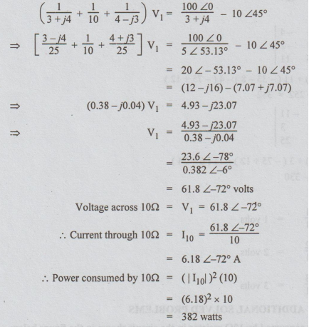
1. Determine the power consumed by 10Ω resistor in the circuit shown in the figure below.
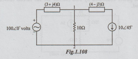
Solution:

There
are two nodes. Node 2 is taken as reference, Let the voltage of node 1 be V1.
The nodal equation is
2. Determine the power consumed by
20
Ω resistor for the circuit shown by
using nodal voltage method.
Solution:
Let V1, V2 and V3 be the voltages of the nodes
1, 2 and 3 respectively.
By
inspection,

V1
= Δ1 / Δ
= 0.0553 / 6.52 × 10-3
=
8.48 volts
V3
= Δ3 / Δ
=
-0.255 / 6.52 × 10-3 = -39.11 volts
Voltage
across 20 Ω = V20 = V1 ~ V3
=
47.59 volts
I20
= 47.59 / 20 = 2.38A
Power
consumed by 20Ω = I2R
=
(2.38)2 × 20
=
113.3 W
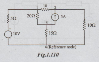
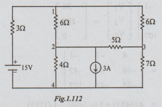
3. Using node voltage method, determine the voltage across the 4Ω resistor.

Solution:
Here,
the voltage source is an ideal one. Hence we cannot solve by writing the matrix.
Let
the node 5 be the reference one.
i.e.,
V5 = 0
So,
V4 = + 12 volts
Let
V1, V2 and V3 be the voltages of the nodes 1,
2 and 3 respectively.
Applying
KCL at node 1, we get,
V1
- V3 / 4 + V1 - V2 / 6 + 2 + 3 = 0
⇒V1 - V3
/4 + V1 - V2 / 6 + 5 = 0
3
(V1 - V3) + 2 (V1 - V2) + 60 = 0
5V1
- 2V2 - 3V3 = -60
10V1
- 4V2 - 6V3 = -120 ..(1)
Applying
KCL at node 2, we get,
V2
- V4 / 3 + V2-V1 / 6 – 2 =0
3 (V2 - V4) + (V2-V1)
= 12
or
3 (V2-I2) + (V2-V1) = 12
or
-V1 +4V2 = 48 ...(2)
Similarly
application of KCL at node 3 yields to
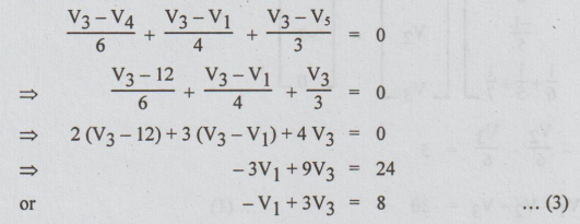
2
(V3 – 12) + 3(V3-V1)+4 V3 = 0
-3V1
+ 9V3 = 24
-V1
+ 3V3 = 8 ...(3)
Adding
(1) and (2), we get
9V1
- 6V3 = - 72...(4)
(3) × 9+ (4)
21V3
= 0
V3
= 0
From
(3) V1 = -8
Current
through 4Ω = V3 - V1/4
=
0- ( -8) / 4
=2A
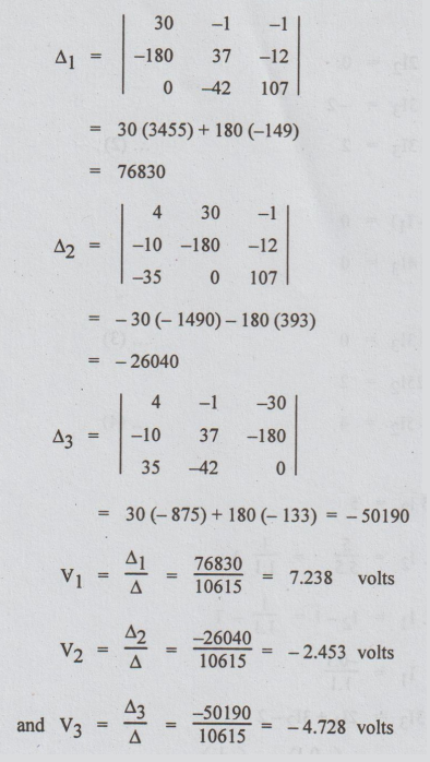
4. For the network of the following
figure, write the nodal equations and solve for the nodal voltages.
Solution:
Let the nodes be numbered as shown. Convert the voltage source into equivalent current
source.
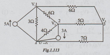
By
inspection we can write that,
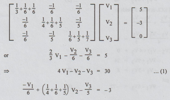
4
V1 - V2 - V3 = 30....(1)
-V1
/ 6 + (1/4 + 1/6 + 1/5 ) V2 - V3/5 = -3
⇒ -10V1 + (15
+ 10 + 12) V2-12V3 = - 180
or
-10V1+ 37V2 - 12V3 = - 180...(2)
and
-V1 / 6 – V2 /5 + 107/210 V3 = 0
=
-35V1 - 42V2 + 107V3 = 0 ...(3)
Putting
the equations (1), (2) and (3) in matrix form,
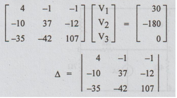
=
4 (3455)+1 (-1490) - 1 (1715)
=
10615
5.
For the circuit given below, use loop analysis, to determine the two loop
currents I1 and I3.

5.
Use loop current analysis and find current through 62 resistor of the network.
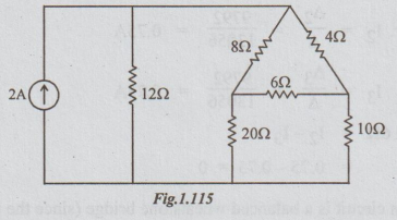
Solution:
First
convert the current source into its equivalent voltage source.
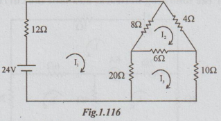
Let
the loop currents be as shown. By inspection,
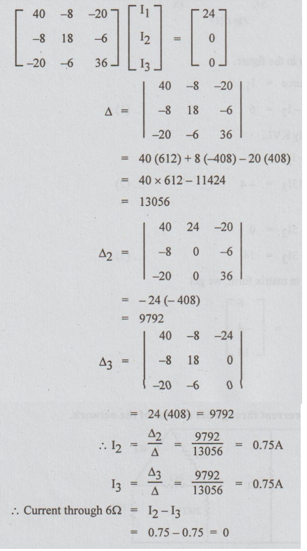
Note:
The given circuit is a balanced wheatstone bridge (since the product of
opposite arms is equal). Hence the current in 6 Ω must be zero.
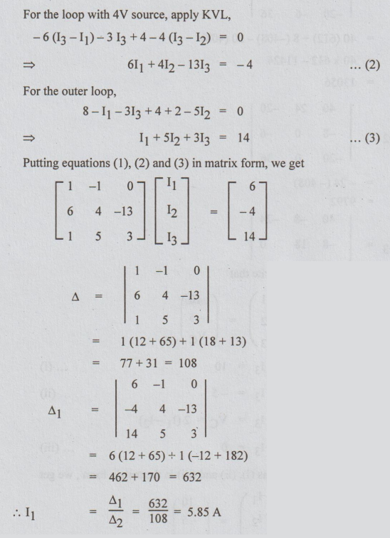
6.
Write loop equations for the following network, and find the current supplied
by 8V source.
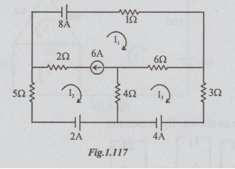
Solution:
Let
the loop currents be as shown in the figure.
The
current through 8V source = I1
I1
– I2 = 6 … (1)
1. Dependent Sources (Controlled Sources): Loop analysis:
Case
(i): Current-controlled voltage sources:
The
loop equations may be written in the same manner as for the circuits with
independent voltage sources. However, there will be an additional equation
giving relationship between the source voltage and the controlling quantity.
Example
1 Determine the current through 42 resistor of the network shown.
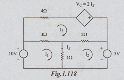
Solution:
Let the loop currents be as shown.
Vc
= 21x (given)
But
Ix = I1 – I2
So,
= Vc 2 (I1 – I2)
Now,
by inspection we write that
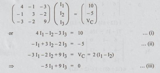
Again
putting the equations (i), (ii) and (iii) in the matrix form, we get
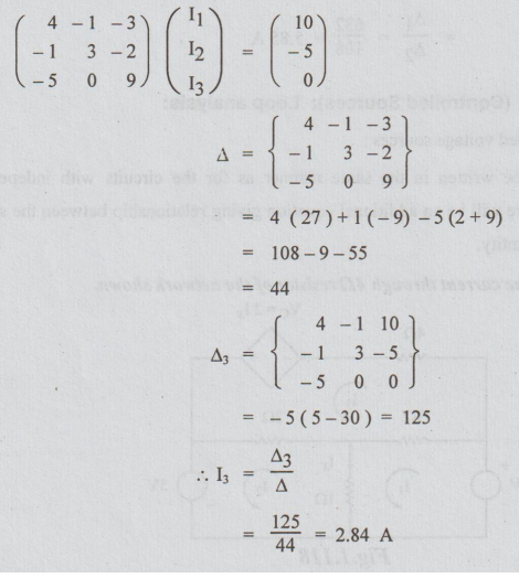
Current
through 4 Ω resistor I3 = 2.84 A
Case
(ii): (Voltage-controlled current source):
Loop
equations can be written in the same manner as for the circuits with
independent sources except for the fact that there will be an additional
equation giving the relationship between the source current and the controlling
quantity.
Example
2 Determine the current through the 100V source in the figure.
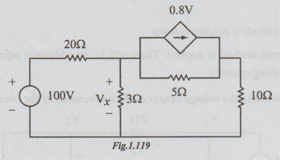
Solution:
Step
1: In the circuit given, the controlled source is
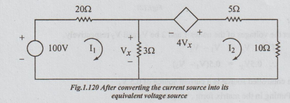
voltage controlled current source. First let us convert it into equivalent
voltage source and draw the circuit as below.

Step
2: Let I, and I2 be the loop currents as shown in the
figure.
Vx
= 3 (I1 – I2)
4
Vx = 12 (I1 – I2)
Step
3: Putting in the matrix form we get,
Electric Circuit Analysis: Unit I: b. Basic circuits analysis : Tag: : Basic circuits analysis - Additional solved problems
Related Topics
Related Subjects

Electric Circuit Analysis
EE3251 2nd Semester 2021 Regulation | 2nd Semester EEE Dept 2021 Regulation