Linear Integrated Circuits: Unit IV: Special ICs
Analog Voltage Divider Circuit
Circuit Diagram, Operating working principle, Derivation
Using log and antilog amplifiers, the circuit can be built to obtain the output proportional to the product of the two input voltages. The circuit is called analog voltage multiplier.
Analog Voltage Divider Circuit
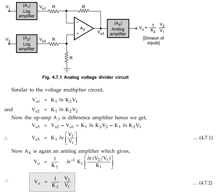
Similar
to analog voltage multiplier, analog voltage divider can be obtained using log
and antilog amplifiers. This circuit gives output which is proportional to the
division of the two input signals. The circuit for the voltage divider is shown
in the Fig. 4.7.1.
Key
Point Thus the output is proportional to the division of
the two analog inputs V1 and V2
Review Questions
1. Explain the voltage divider circuit using op-amp.
Linear Integrated Circuits: Unit IV: Special ICs : Tag: : Circuit Diagram, Operating working principle, Derivation - Analog Voltage Divider Circuit
Related Topics
Related Subjects

Linear Integrated Circuits
EE3402 Lic Operational Amplifiers 4th Semester EEE Dept | 2021 Regulation | 4th Semester EEE Dept 2021 Regulation