Electric Circuit Analysis: Unit I: b. Basic circuits analysis
Analysis of ac circuit
It is assumed that the sinusoidally varying voltage is connected to (a) purely resistive (b) purely inductive and (c) purely capacitive circuits.
ANALYSIS OF AC CIRCUIT
It
is assumed that the sinusoidally varying voltage is connected to
(a)
purely resistive
(b)
purely inductive and
(c)
purely capacitive circuits.
In
each case it is required to find the following quantities
1.
The expression for the instantaneous current.
2.
The polar form of voltage and current
3.
The phasor diagram.
4.
Ratio of voltage to current
5.
Average power
6.
Phase angle between voltage and current and hence power factor.
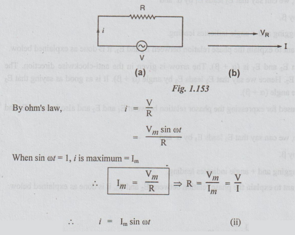
1. Purely Resistive Circuit Excited by a Sinusoidally Varying Voltage
Let,
v = Vm sin ot be the applied voltage
R
= Resistance of the circuit
i
= instantaneous current flowing in the circuit
By
observing equations (i) and (ii) we can conclude that the voltage applied and
the current flowing, in a purely resistive circuit are in phase (it is because
both V and I are sinusoidally varying quantities and also the angles are same).
To
represent V and I in polar form
Let
V = RMS value of the voltage = Vm/√2
I
= RMS value of the current = Im/√2
Now,
writing equations (i) and (ii) in polar form, we get
V
= | V | ∠o ... (iii)
I
= |V| ∠ o. .. (iv)
With
the help of the above equations, phasor diagram can be drawn as shown in the
fig 2.28 (b).
Impedance
In the case of A.C circuits, ratio of V to I is called impedance (Z)
From
equations (iii) and (iv)
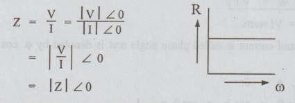
If
the angle of Z is zero as shown above,,
Z
= R
i.e;
Z = R ∠ 0
This
Z is independent of frequency. The instantaneous power = w.
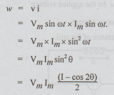
Maximum
instantaneous value at (θ = π/2) = VmIm
Average
power P = W
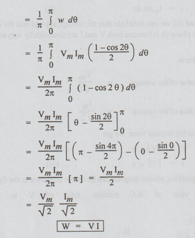
(i.e) Average power = W = VI watts
The
angle between voltage and current is called phase angle and is denoted by ϕ.
cos ϕ is called power factor.
In
this circuit, ϕ = 0.
Power
factor (p.f) = cos ϕ = cos 0 = 1
(i.e).,
the circuit is said to have unity power factor (u.p.f).
2. Circuit Consisting of Pure Inductance Excited by a Sinusoidally Varying Voltage
Let
v = Vm sin ot be the applied voltage ... (i)
i
= instantaneous current
L
= self-inductance of the coil.
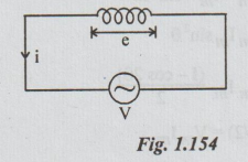
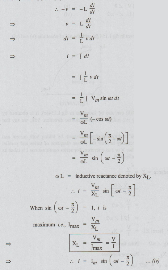
We
know that e = - L di/dt … (ii)
But,
according to Lenz's law, e opposes the applied voltage
i.e.,
From
equations (ii) and (iii),
Both
equations (i) and (iv) are sinusoidally varying quantities. Hence, we can
compare these equations for knowing the phase relation. As the angle of i is
less than that of v bу π/2, we say that current lags behind voltage by π/2.
As
already mentioned minus angle (for alternating quantities) indicates lagging.
To
represent V and I in polar form
We
take V as reference. With the help of equations (i) and (iv) we write,
V
= |V| ∠ 0 … (v)
and
I = | I | ∠ - π/2
… (vi)
Phasor
diagram
The
phasor diagram can be drawn as shown in fig 1.154 (b) with the aid of equations
(v) and (vi).
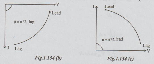
The
phasor diagram drawn in fig 1.154(b) can also be shown as in fig 1.154(c). It
is obtained by rotating the phasor diagram in 1.154(b) by π/2 radians in
anti-clockwise direction. Still, we say that current lags behind the voltage by
л/2.
(Note:
The reader should know as how to draw the phasor diagram by taking both current
and voltage as reference. This knowledge is necessary to draw the phasor
diagrams of series and parallel circuits. For single elements we can take
either V or I as reference. For series combinations I is taken as reference.
For parallel circuit V is taken as reference).
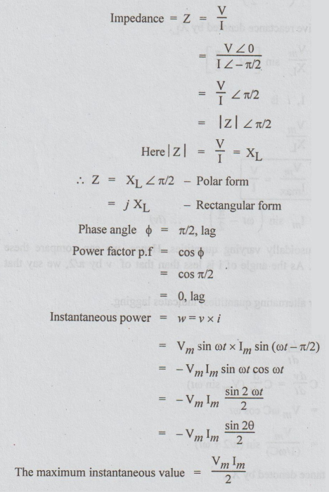
The
instantaneous power w varies at twice the supply frequency.
Average
power =
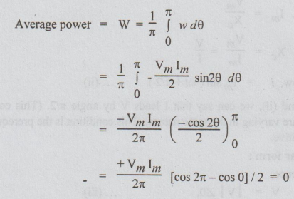
Thus,
the average power dissipated by the pure inductor = 0.
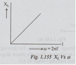
XL
is a function of frequency. XL varies linearly with frequency. For
D.C. circuits, frequency is zero and hence XL
The
variation of XL with frequency is as shown in fig.
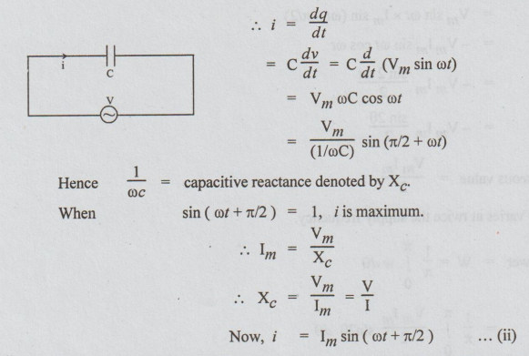
Purely Capacitive Circuit Excited by Sinusoidally Varying
Voltage
Let
v= Vm sin ωt
C
= Capacitance of the capacitor
i
= instantaneous current
By
definition, charge q = Cv
By
observing equations (i) and (ii), we can say that I leads V by angle π/2. (This
comparison is possible because both equations are varying in the same nature).
This condition is the prerequisite for the comparison. The angle of i is
positive.
To
represent V and I in the polar form:
Taking
V as reference,
V
= | V | ∠ 0, ... (iii)
and
I = | I | 2π/2 ... (iv)
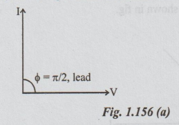
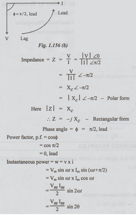
Phasor
diagram:
Equations
(iii) and (iv) can be represented as phasors shown in the fig. 1.156(a).
For
a series circuit, current is same through all the elements. For drawing phasor
diagram for series circuits, as already mentioned, I is taken as reference.
Thus, the phasor diagram in Fig.1.156(a) can be re-drawn as in Fig.1.156(b).
Still, the current leads the voltage bу л/2.
The
frequency of instantaneous power is twice that of voltage or current. Maximum
instantaneous power
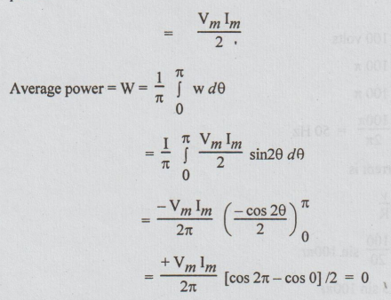
Thus
the average power dissipated by purely capacitive circuit = 0.
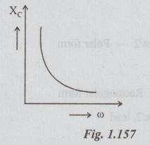
We
know that Xc = 1 / ωC
Xc
is a function of frequency.
As
frequency increases, Xc decreases.
The
relation between the two will be a rectangular hyperbola.
Electric Circuit Analysis: Unit I: b. Basic circuits analysis : Tag: : - Analysis of ac circuit
Electric Circuit Analysis: Unit I: b. Basic circuits analysis
Under Subject

Electric Circuit Analysis
EE3251 2nd Semester 2021 Regulation | 2nd Semester EEE Dept 2021 Regulation
Related Subjects

Professional English II
HS3251 2nd Semester 2021 Regulation | 2nd Semester Common to all Dept 2021 Regulation

Statistics and Numerical Methods
MA3251 2nd Semester 2021 Regulation M2 Engineering Mathematics 2 | 2nd Semester Common to all Dept 2021 Regulation

Engineering Graphics
GE3251 eg 2nd semester | 2021 Regulation | 2nd Semester Common to all Dept 2021 Regulation

Physics for Electrical Engineering
PH3202 2nd Semester 2021 Regulation | 2nd Semester EEE Dept 2021 Regulation

Basic Civil and Mechanical Engineering
BE3255 2nd Semester 2021 Regulation | 2nd Semester EEE Dept 2021 Regulation
Electric Circuit Analysis
EE3251 2nd Semester 2021 Regulation | 2nd Semester EEE Dept 2021 Regulation

Physics for Electronics Engineering
PH3254 - Physics II - 2nd Semester - ECE Department - 2021 Regulation | 2nd Semester ECE Dept 2021 Regulation

Electrical and Instrumentation Engineering
BE3254 - 2nd Semester - ECE Dept - 2021 Regulation | 2nd Semester ECE Dept 2021 Regulation

Circuit Analysis
EC3251 - 2nd Semester - ECE Dept - 2021 Regulation | 2nd Semester ECE Dept 2021 Regulation

Materials Science
PH3251 2nd semester Mechanical Dept | 2021 Regulation | 2nd Semester Mechanical Dept 2021 Regulation

Basic Electrical and Electronics Engineering
BE3251 2nd semester Mechanical Dept | 2021 Regulation | 2nd Semester Mechanical Dept 2021 Regulation

Physics for Civil Engineering
PH3201 2021 Regulation | 2nd Semester Civil Dept 2021 Regulation

Basic Electrical, Electronics and Instrumentation Engineering
BE3252 2021 Regulation | 2nd Semester Civil Dept 2021 Regulation

Physics for Information Science
PH3256 2nd Semester CSE Dept | 2021 Regulation | 2nd Semester CSE Dept 2021 Regulation

Basic Electrical and Electronics Engineering
BE3251 2nd Semester CSE Dept 2021 | Regulation | 2nd Semester CSE Dept 2021 Regulation

Programming in C
CS3251 2nd Semester CSE Dept 2021 | Regulation | 2nd Semester CSE Dept 2021 Regulation