Electric Circuit Analysis: Unit V: Resonance and coupled circuits
Analysis of coupled circuits
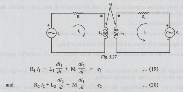
Each circuit contains a voltage source. As both currents i, and i2 enter the coils through the dotted ends, M is taken as positive. By applying KVL, the two loop equations may be written as below
ANALYSIS OF COUPLED CIRCUITS
Consider
the coupled circuits.
Each
circuit contains a voltage source. As both currents i, and i2 enter the coils
through the dotted ends, M is taken as positive. By applying KVL, the two loop
equations may be written as below:
In
the sinusoidal steady state the above equations become,
(R1
+ jωL1) I1 + jωMI2 = E1 …
(21)
joM
I1 + (R2 + jωL2) = E2 … (22)
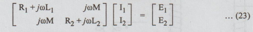
In
the matrix form, the last two equations may be written as,
The
equations (21) & (22) may be written as
[R1
+ jω (L1 – M + M) I1 ] E1 … (24)
and
jωMI1 + (R2 – jω (L2 – M + M) ] I2
… (25)
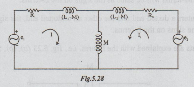
The
coupled circuit of fig. 5.20 may be now re-drawn as in fig. 5.28. It is called
conductively coupled equivalent circuit of the mutually coupled circuit. It is
so called because of the common conducting element M.
Electric Circuit Analysis: Unit V: Resonance and coupled circuits : Tag: : - Analysis of coupled circuits
Related Topics
Related Subjects

Electric Circuit Analysis
EE3251 2nd Semester 2021 Regulation | 2nd Semester EEE Dept 2021 Regulation