Electrical Machines II: UNIT II: Synchronous Motor
Analysis of Phasor Diagram
Synchronous Motor
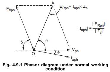
Consider a phasor diagram with normal excitation i.e. such a current through field winding which will produce flux that will adjust magnitude of Ebph same as Vph.
Analysis of Phasor Diagram
Consider
a phasor diagram with normal excitation i.e. such a current through field
winding which will produce flux that will adjust magnitude of Ebph
same as Vph.
Let
δ be the load angle corresponding to the load on the motor. So from the exact
opposing position of Ebph with respect to Vph. Ebpb gets
displaced by angle δ.
Vector
difference of Ebph and Vph,
gives the phasor which represents Ia Zs, called ERph-
Now
Zs = Ra + j Xs |Ω| = |ZS| ∠θΩ
where
Ra = Resistance of stator per phase
Xs
= Synchronous reactance of stator per phase
i.e
θ ta -1 Xs
/ Ra
and
|ZS| = Ra2 + X52 Ω
This
angle ' θ ' is called internal
machine angle or an impedance angle.
The
significance of ' θ
' is that it tells us that phasor Iaph lags behind ERph
i.e. Ia Zs by angle θ. Current always lags in case of
inductive impedance with respect to voltage drop across that impedance. So
phasor Iapb can be shown lagging with respect to ERpb by angle θ. Practically Ra
is very small compared to Xa and hence θ tends to 90°.
Key Point The power factor
at which motor is running, gets decided by the angle between Vph and
Iaph, shown. This angle is denoted as ϕ and
called power factor angle.
ϕ
= Vph Λ Iaph
=
Power factor angle
and
cos ϕ = Power factor at which motor is working
The
nature of this p.f. is lagging if Iaph lags Vph by angle ϕ.Phasor
diagram indicating all the details is shown in the Fig.4.9.1.
Electrical Machines II: UNIT II: Synchronous Motor : Tag: Engineering Electrical Machines - II : Synchronous Motor - Analysis of Phasor Diagram
Related Topics
Related Subjects

Electrical Machines II
EE3405 Machine 2 EM 2 4th Semester EEE Dept | 2021 Regulation | 4th Semester EEE Dept 2021 Regulation