Electromagnetic Theory: Unit III: (b) Magnetic Forces, Magnetic Materials and Inductance
Applications of Magnetic
Applications : 1. Ferrite Cores 2. Magnetic Recording 3. Magnetic Shielding
Applications
1. Ferrite Cores
•
The transformers are the devices which transform voltages and currents and thus
impedances. Practically in most of the cases core is made up of ferromagnetic
material like iron which is used to produce low reluctance path. In some
applications, it is necessary to have a core with a complicated shape. It is
found that it is very difficult to prepare a very complicated shaped core using
solid material like iron. To overcome this limitation ferrite materials are
used in place of iron.
•
Basically ferrite is a mixture of powered ferromagnetic materials. Then the
mixture is moulded into the desired shape and then it is intered. In general,
ferrite can be obtained from any ferromagnetic material. The ferromagnetic
materials are the most useful magnetic materials which have relative
permeability greater than 1 and tend to thousands or even higher. Some of the
important ferromagnetic materials and their relative permeabilities are as given
below.

•
Most of the ferrites are obtained from iron oxide Fe3O4
i.e. magnetite. Iron oxide like Fe3O4 is mixed with
bivalent compound like Barium Oxide (BaO), Nickel Oxide (NiO), Manganese Oxide (MnO)
etc. to obtain ferrite material. Depending upon materials used and processes
used, the ferrites obtained by mixing iron oxide with bivalent compounds can be
made to have any shape and size and these ferrites can have properties of solid
material. The main advantage of sintering process used to bind these compounds
is that, the ferrite become hard and brittle. They can be further worked with
grinding process only.
•
The important properties of ferrites are as follows.
i)
The conductivity of ferrite is very low. It is generally below 10_ 5 S/m. Some
of the ferrites show conductivity of the order of 1 S/m.
ii)
Ferrite cores are used in the applications where frequency of operation is
higher.
iii)
The coercive field intensity of ferrite is relatively low and typically it is
below 100 A/m.
iv)
The ferrites have relative permeability between 10 and 10000.
v)
The ferrites show square magnetization curve and the remnant flux density low
and it is below 0.5 T.
2. Magnetic Recording
•
The most useful application of the magnetic materials is the recording of
signals. Inspite of variations in composition of different magnetic recording
media, the basic principle of recording remain same in all the methods. In the
process of magnetic recording, the magnetic particles on the substrate are oriented
differently with the aid of external magnetic field. There are two methods to
produce magnetic medium for recording such as tape and disk.
i)
In first method, the recording medium is coated with a base material consisting
ferromagnetic particles in binding material. In this method, each particle is
suspended independently. The domains of these particles can be oriented with
the help of external magnetic fields. This method is generally used in magnetic
tapes.
ii)
In second method, a ferromagnetic alloy is deposited on the non-ferromagnetic
base material in the form of thin layer.
This method is mostly used for disks. Various alloys of iron and cobalt are
used as materials for disks.
•
In both the methods, the particles are diluted in a binder to the extent of 25
to 50 % of volume and then coated on a thin substrate film of polyethelene or
aluminium disks. The binder is very important as it contains lubricating
substance which prevent magnetic tape or recording head from damage. There is
no limitation on the number of particles of ferromagnetic materials. Typical
ferromagnetic materials used are cobalt, nickel, iron and iron oxides. But most
of the tapes are made up of Fe2O3.
a.
Principle of Tape Recorders
•
The principle of the magnetic tape recording is as follows. When a magnetic
tape is passed through a recording head, the signal to be recorded appears as
some magnetic pattern on the tape. This magnetic pattern is in accordance with
the variations of original recording current. The recorded signal can be
reproduced back by passing the same tape through a reproducing head where the
voltage is induced corresponding to the magnetic pattern on the tape.
•
When the tape is passed through the reproducing head, the head detects the
changes in the magnetic pattern i.e. magnetization. The change in magnetization
of particles produces change in the reluctance of the magnetic circuit of the
reproducing head, inducing a voltage in its winding. The induced voltage
depends on the direction of magnetisation and its magnitude on the tape. The
emf, thus induced is proportional to the rate of change of magnitude of
magnetisation i.e. e ɑ N (dϕ / dt)
where
N = Number of turns of the winding on reproducing head
ϕ
= Magnetic flux produced.
•
Suppose the signal to be recorded is Vm sin ωt.
Thus,
the current in the recording head and flux induced will be proportional to this
voltage. It is given by,
ϕ
= k1 • Vm sin ωt, where
k1
= constant
•
Above pattern of flux is recorded on the tape. Now , when this tape is passed
through the reproducing head, above pattern is regenerated by inducing voltage
in the reproducing head winding. It is given by,

•
Thus, the reproduced signal is equal to derivative of input signal and it is
proportional to flux recorded and frequency of recorded signal.
b.
Methods of Recording
•
The methods used for magnetic tape recording used for instrumentation purposes
are as follows :
i)
Direct Recording
ii)
Frequency Modulation Recording
iii)
Pulse Duration Modulation Recording
•
For instrumentation purposes mostly frequency modu lation recording is used.
The pulse duration modulation recording is generally used in the systems for
special applications where large number of slowly changing variables have to be
recorded simultaneously.
i)
Direct Recording :
•
This method of recording is the simplest one. This method usually requires one
tape track for each channel. The input signal to be recorded is amplified and
mixed with high frequency bias. This signal is then fed to recording head as
recording current.
•
The magnetic pattern recorded on the magnetic tape is directly proportional to
the magnetic flux density produced at the air gap. The input current i.e.
recording current is sinusoidal. But the magnetisation pattern developed during
recording is non-sinusoidal. Thus the current in the winding and flux density
in the air gap are having non-linear relationship between them. The
relationship between winding current and flux density in air gap is as shown in
Fig. 8.13.1.

•
The distortion can be avoided by applying a high frequency bias of constant
frequency with the signal input. The amplitude and frequency of this high
frequency bias is greater than maximum amplitude and highest frequency of the
signal to be recorded. The bias frequency is generally 4 times greater than the
highest frequency while the amplitude is about 5 to 30 times greater than the
input signal current. The exact value of bias amplitude depends on tape and
head characteristics.
•
The mixing of bias and the input signal is accomplished by using a linear
mixing process. The peak value of the combined signal is limited in such a way
that it lies on the linear portion of B-H curve. This signal is passed through
recording signal as shown in Fig. 8.13.2.

• The reproducing head exactly reproduces same
waveform. This reproduced waveform is then passed through filter block which
removes unwanted high frequency components and gives original waveform. This
signal may be amplified to get suitable higher magnitude.
•
The output voltage of the reproducing head is directly proportional to the
frequency of input signal. Hence direct recording procedure can not be used to
record d.c. signal (having zero frequency) as voltage developed in reproducing
head is zero. As frequency of input signal decreases, the output voltage in
reproducing head decreases. Thus, there is a limitation on lower operating
frequency. Below certain limit of frequency, voltage in reproducing head will
be equal to noise in the system. If the signal with frequency less than this
frequency is used, signal will be completely overcome by the noise.
•
Similar to lower frequency, there is a limitation on higher frequency. The
higher frequency is limited by gap of length of reproducing head. When the tape
passes the air gap of the reproducing head, the wavelength of the tape is given
by,
λ
= (V / f) m
where
V = Speed of tape in m/sec
f
= Frequency of recorded signal in Hz.
• From above equation it is clear that when
speed of tape increases, the wavelength A also increases at any given
frequency. If the air gap in the reproducing head is significant in relation
with wavelength A then the small changes in the signal can not be reproduced.
Thus the air gap must be small compared to the wavelength of the highest
frequency to be reproduced.
•
The output voltage in the reproducing head increases with frequency. This
continues till the length of the gap equals half value of the recorded
wavelength. After this, output voltage decreases rapidly and then becomes zero.
This is called as gap effect which restricts high frequency response of the
tape recorder.
Advantages
of Direct Recording :
i)
This has a wide frequency response from 50 Hz to 2 MHz for tape speed of 3.05
m/s. It has a very high bandwidth.
ii)
It requires simple and cheap electronic circuits only.
iii)
It has a good dynamic ratio without increase in distortion.
iv)
It is used to record signals such as spectrum analysis of noise where the
information is in relation with frequency and amplitude.
v)
It can be used to record voice signals.
Disadvantages
of Direct Recording :
i)
Due to certain random surface inhomogeneities in the tape, there may be
amplitude instability in the recorded signal.
ii)
Due to poor manufacturing and dirt on the tape, some portion may not be
perfectly recorded.
iii)
It can be used only when maximum bandwidth is needed.
iv)
It can not record dc signals.
ii)
Frequency Modulation (FM) Recording :
The
major disadvantage of direct recording is that it is difficult to record dc
signals. This difficulty is overcome by using frequency modulation recording in
which accurate dc response is obtained.
Principle
of Operation :
•
In the FM recording, the carrier frequency 1^- is modulated by the input
signal. FM recording uses the variation of frequency to carry the required
information instead of varying the amplitude. The modulated signal is then
recorded using the recording head in normal way. The reproducing head
reproduces the signal in normal way. This reproduced signal is passed through
FM demodulator, low pass filter to get original signal.
Operation
:
•
The basic FM recording system is as shown in Fig. 8.13.3.
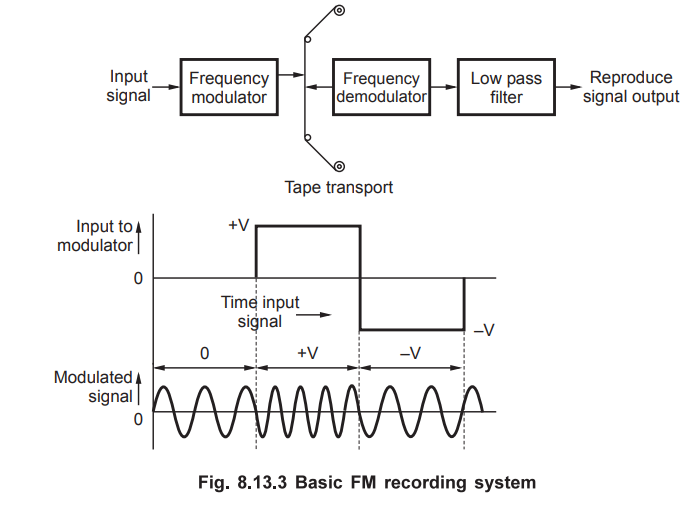
•
In this system, the carrier frequency is called as center frequency fC.
This frequency is modulated by the level of the input signal. When the input
signal is zero, the modulation contains only the center frequency oscillation.
The positive input voltage deviates the carrier
frequency by specified percentage in one direction. The negative voltage
deviates the carrier frequency by specified percentage in other direction.
For dc inputs the modulated output is a signal of constant frequency and for ac
inputs the modulated output is a signal of variable frequency. The frequency
variation is directly proportional to the amplitude of input signal. During the
playback, the output of the reproducing head is passed through FM demodulator.
The demodulated signal is passed through the filter which removes the carrier
frequency fC and the unwanted signals. The FM demodulator converts
the difference between center frequency and frequency on the tape, to a voltage
proportional to frequency difference. Thus the FM recording enables to record
signals from dc to several thousand Hz.
•
The central frequency is selected with respect to the tape speed. The frequency
deviation selected is ± 40 % about carrier frequency. When the tape speed is
changed, there is proportional change in the carrier frequency. So for the dc
signal the wave length λ remains same as
λ = V / f and as speed V changes, the frequency also changes in proportion.
•
There are two factors related to FM recording
i)
Percentage deviation ii) Deviation ratio
i)
Percentage Deviation
•
It is defined as ratio of carrier deviation to center frequency. It is denoted
by M.
Percentage
Deviation = M = Δf / fC × 100
•
It is also called as Modulation Index.
ii)
Deviation Ratio :
•
It is the ratio of carrier deviation from center frequency to the signal
frequency or modulating frequency. It is denoted by δ.
δ
= Δf / fm where fm = Modulating frequency.
Advantages
of FM Recording
i)
FM recording is useful mainly to record dc components.
ii)
FM recording has wide frequency range from Hz to several kHz.
iii)
In FM recording, drop out effects due to inhomogeneities are not possible.
iv)
Amplitude variation is neglected in FM recording and input signal is correctly
recorded.
v)
FM recording is extensively used for recording non electrical quantities such
as force, pressure etc.
vi)
FM recording is extensively used for multiplexing in the instrumentation and
process system.
Disadvantages
of FM Recording
i)
The tape speed fluctuations affect the FM recording.
ii)
The circuitry used for FM recording is complicated as compared to that of
direct recording.
iii)
FM systems have limited frequency response.
iv)
For FM recording high tape speed are required.
v)
Better recording requires high quality tape transport and speed control
mechanisms.
vi)
It is comparatively expensive.
iii)
Pulse Duration Modulation Recording (PDM)
•
The pulse duration modulation is also called as pulse width modulation. The
principle of operation is that the amplitude and starting time of each pulse of
a signal is kept constant while width of pulse is made proportional to
amplitude of signal at that instant.
•
In this recording system, the input signal is converted to a pulse at the sampling
instant. The width of each pulse is dependent on the a mplitude of the signal
at that instant. The sampled signal is recorded at various instants instead of
recording instantaneous values continuously. On playback original signal can be
obtained by passing re corded signal to appropriate filter.
Advantages
of Pulse Duration Modulation Recording
i)
PDM recording is mainly useful when large number of information from various
channels is to be recorded simultaneously.
ii)
PDM recording has high accuracy.
iii)
PDM recording has high signal to noise ratio.
Disadvantages
of Pulse Duration Modulation Recording
i)
It has limited frequency response.
ii)
Because of complex circuitry, reliability of recording is low.
iii)
Only useful to record several slowly varying signals simultaneously.
3. Magnetic Shielding
•
In many applications, it is necessary to protect instruments from the effects
of external magnetic fields. Often it is required to measure very low magnetic
fields which are less than geomagnetic fields. In some applications, we may
require to calibrate magnetic devices. In such applications, we cannot get
correct results if there are external magnetic fields around the measuring
instruments. In many applications like Magnetic Resonance Imaging (MRI), the
electromagnets produce very large magnetic field of the order of 1 to 3 T. So
due to such high magnetic fields, the measuring instruments, testing
equipments, computers and even a human operator exposed to the fields, get
affected. So it is very much needed to protect all these elements against high
magnetic fields. This is done by magnetic shielding.
•
In practice there is no known insulator for the magnetic flux. Suppose we place
a non-magnetic material in the magnetic field, then it is observed that there
is no appreciable change in the magnetic flux. For example, if we use glass
plate in between magnetic flux, then there is no considerable effect on the
magnetic field although the glass is good insulator of electricity. Then to
protect the equipments against the external magnetic fields, a low reluctance
path is provided using a piece of soft iron having high permeability such that
the magnetic field is directed away from the area that is to be shielded. This
is analogous to a short branch in an electric circuit so that the large current
flows through the short branch protecting other branch with circuit elements
connected in parallel with it.
•
Suppose we want to contain the field inside the structure and also shield the
interior of the structure from external mangetic fields. Consider a coil inside
a shielded structure placed at the center as shown in the Fig. 8.13.4.
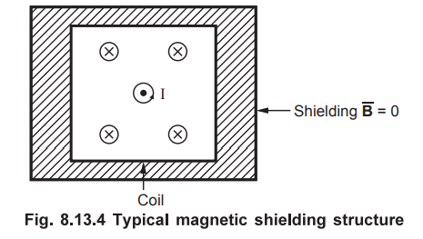
The
current through the coil at center produces a magnetic field. To avoid the
effect of this field outside the structure, a box of iron is placed around
coil. The iron has high permeability i. e. low reluctivity and hence most of
the field passes through the box of iron. Thus the field outside the iron box
is zero. Also the same structure is used to shield the interior of the box from
the external magnetic fields.
•
In an application of MRI set-up, being huge set-up, the magnetic shield is
placed within the walls of the room where the equipment is placed. Along with
the walls, floor as well as ceiling are also provided with iron of say 50 mm
thick (serving as magnetic shield) for a room of 4 × 4 × 2.5 m. The total
volume of iron is typically 3.5 m3. Using such magnetic shielding,
the magnetic field is contained within the room. It also protects the area
inside the room from the magnetic fields produced outside the room.
Review Questions
1. Explain principle of magnetic recording.
2. Write a note on ferrite cores.
3. Explain magnetic shielding in brief.
Electromagnetic Theory: Unit III: (b) Magnetic Forces, Magnetic Materials and Inductance : Tag: : - Applications of Magnetic
Related Topics
Related Subjects

Electromagnetic Theory
EE3301 3rd Semester EEE Dept | 2021 Regulation | 3rd Semester EEE Dept 2021 Regulation