Electrical Machines II: UNIT I: b. Armature Reaction and Regulation of Alternators
Armature Reaction
Synchronous Generator or Alternators
The flux produced by the armature is called armature flux
Armature Reaction
When
the load is connected to the alternator, the armature winding of the alternator
carries a current. Every current carrying conductor produces its own flux so
armature of the alternator also produces its own flux, when carrying a current.
So there are two fluxes present in the air gap, one due to armature current
while second is produced by the field winding called main flux. The flux
produced by the armature is called armature flux.
Key Point : So effect of the
armature flux on the main flux affecting its value and the distribution is
called armature reaction.
The
effect of the armature flux not only depends on the magnitude of the current
flowing through the armature winding but also depends on the nature of the
power factor of the load connected to the alternator.
Let
us study the effect of nature of the load power factor on the armature
reaction.
1. Unity Power Factor Load
Consider
a purely resistive load connected to the alternator, having unity power factor.
As induced e.m.f. Eph drives a current of Iaph and load
power factor is unity, Eph and Iaph are in phase with
each other.
If
ϕ f is the main flux produced by the field winding responsible for
producing Eph then Eph lags ϕ f by 90°
Now
current through armature Ia, produces the armature flux say ϕ a
. So flux ϕ a and Ia are always in the same
direction.
This
relationship between ϕ f , ϕa
Eph and Iaph can be shown in the phasor diagram. Refer to
the Fig. 2.5.1.
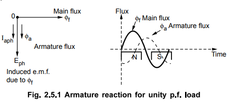
It
can be seen from the phasor diagram that there exists a phase difference of 90°
between the armature flux and the main flux. The waveforms for the two fluxes
are also shown in the Fig. 2.5.1. From the waveforms it can be seen that the
two fluxes oppose each other on the left half of each pole while assist each
other on the right half of each pole. Hence average flux in the air gap remains
constant but its distribution gets distorted.
Key Point : Hence such
distorting effect of armature reaction under unity p.f. condition of the load
is called cross magnetising effect of armature reaction.
Due
to such distortion of the flux, there is small drop in the terminal voltage of
the alternator.
2. Zero Lagging Power Factor Load
Consider
a purely inductive load connected to the alternator having zero lagging power
factor. This indicates that Iaph driven by Eph, lags Eph by 90° which is the
power factor angle ϕ.
Induced
e.m.f. Eph lags main flux ϕ f by 90o while ϕ a
is in the same direction as that of Ia. So the phasor diagram and the
waveforms are shown in the Fig 2.5.2
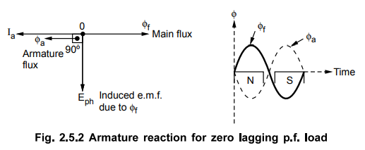
It
can be seen from the phasir diagram that the armature flux and the main flux
are exactly in opposite direaction to each other.
Key Point So armature flux
tries to cancel the main flux. Such an effect of armature reaction is called
demagnetising effect of the armature reaction.
As
this effect causes reduction in the main flux, the terminal voltage drops. This
drop in the terminal voltage is more than the drop corresponding to the unity
p.f. load.
3. Zero Leading Power Factor Load
Consider
a purely capacitive load connected to the alternator having zero leading power
factor. This means that armature current Iaph driven by Eph,
leads Eph by 90°, which is the power factor angle ϕ.
Induced
e.m.f. Eph lags ϕ f by 90° while Iaph and ϕ a
are always in the same direction. The phasor diagram and the waveforms are
shown in the Fig. 2.5.3.
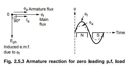
It
can be seen from the phasor diagram and waveforms shown in the Fig. 2.5.3, the
armature flux and the main field flux are in the same direction i.e. they are
helping each other. This results into the addition in main flux.
Key Point : Such an effect of
armature reaction due to which armature flux assists field flux is called
magnetising effect of the armature reaction.
As
this effect adds the flux to the main flux, greater e.m.f. gets induced in the
armature. Hence there is increase in the terminal voltage for leading power
factor loads.
For
intermediate power factor loads i.e. between zero lagging and zero leading the
armature reaction is partly cross magnetising and partly demagnetising for
lagging power factor loads or partly magnetising for leading power factor
loads.
4. Armature Reaction Reactance (Xar)
In
all the conditions of the load power factors, there is change in the terminal
voltage due to the armature reaction. Mainly the practical loads are inductive
in nature, due to demagnetising effect of armature reaction, there is reduction
in the terminal voltage. Now this drop in the voltage is due to the interaction
of armature and main flux. This drop is not across any physical element.
But
to quantify the voltage drop due to the armature reaction, armature winding is
assumed to have a fictitious reactance. This fictitious reactance of the
armature is called armature reaction reactance denoted as Xar Ω /ph.
And the drop due to armature reaction can be accounted as the voltage drop
across this reactance as Ia Xar.
Key Point : The value of this
reactance changes as the load power factor changes, as armature reaction
depends on the load power factor.
Review Question
1. What is armature reaction in alternators ? Explain it for
different power factor conditions. AU :
May-03, 09, 12, 16, Pec.-07, 15, Marks 6
Electrical Machines II: UNIT I: b. Armature Reaction and Regulation of Alternators : Tag: Engineering Electrical Machines - II : Synchronous Generator or Alternators - Armature Reaction
Related Topics
Related Subjects

Electrical Machines II
EE3405 Machine 2 EM 2 4th Semester EEE Dept | 2021 Regulation | 4th Semester EEE Dept 2021 Regulation