Linear Integrated Circuits: Unit III: Applications of Op-amp
Astable Multivibrator using Op-amp
Working Principle, Pulse, Circuit Diagram, Solved Example Problems | Operational amplifier
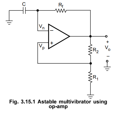
In this section we are going to study astable multivibrator operation using op-amp. Fig. 3.15.1 shows astable multivibrator circuit using op-amp. It looks like a comparator with Hysteresis (Schmitt trigger), except that the input voltage is replaced by a capacitor.
Astable Multivibrator using Op-amp.
In
this section we are going to study astable multivibrator operation using
op-amp. Fig. 3.15.1 shows astable multivibrator circuit using op-amp. It looks
like a comparator with Hysteresis (Schmitt trigger), except that the input
voltage is replaced by a capacitor. The circuit has a time dependent elements
such as resistance and capacitor to set the frequency of oscillation.
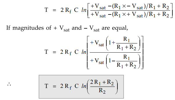
As
shown in the Fig. 3.15.1 the comparator and positive feedback resistors R1 and
R 2 form an inverting Schmitt trigger.
When
Vo is at +Vsat, the feedback voltage is called the upper
threshold voltage VUT and is given as
VUT
= R1. (+Vsat) / R1 + R2 ... (3.15.1)
When
Vo is at -Vsat, the feedback voltage is called the
lower-threshold voltage VLT and is given as
VLT = R1. (- Vsat) / R1 + R2 ... (3.15.2)
When
power is turn ON, Vo automatically swings either to +Vsat
or to -Vsat since these are
the only stable states allowed by the Schmitt trigger. Assume it swings to +Vsat.
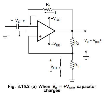
With Vo = +Vsat we have Vp = VUT
nnd capacitor starts charging towards +Vsat through the feedback path provided
by the resistor Rf to the inverting (-) input. This is illustrated
in Fig. 3.15.2 (a). As long as the capacitor voltage VC is less than
VUT the output voltage remains at +Vsat.
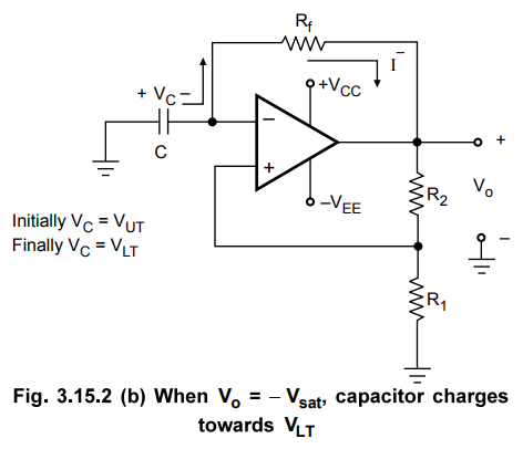
As
soon as VC charges to a value slightly greater than VUT /
the (-) input goes positive with respect to the (+) input. This switches the
output voltage from +Vsat to -Vsat and we have Vp = VLT , which is
negative with respect to ground. As Vo switches to -Vsat, capacitor
starts discharging via Rf, as shown in the Fig. 3.15.2 (b).
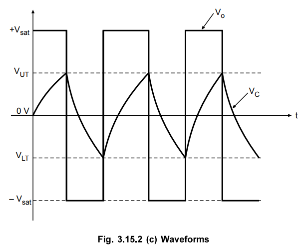
The
current I - discharges capacitor to 0 V and recharges capacitor to
Finally VC VLT. When VC becomes slightly more
negative than the feedback voltage VLT, output voltage Vo
switches back to +Vsat. As a result, the condition in Fig. 3.15.2
(a) is reestablished except that capacitor now has a initial charge equal to VLT.
The capacitor will discharge from VLT to 0 V and then recharge to VUT,
and the process is repeating. Once the initial cycle is completed, the
waveforms become periodic, as shown in the Fig. 3.15.2(c).
1. Frequency of Oscillation
The
frequency of oscillation is determined by the time it takes the capacitor to
charge from VUT to VLT and vice versa. The voltage across
the capacitor as a function of time is given as
VC(t)
= Vmax + (Vinitial - Vmax)e(-t/T) ... (3.15.3)
Where
VC(t) is the instantaneous voltage across the capacitor.
Vinitial
is the initial voltage
Vmax
is the voltage toward which the capacitor is charging.
Let
us consider the charging of capacitor from VLT to VUT,
where VLT is the initial voltage, VUT the instantaneous
voltage and +Vsat is the maximum voltage. At t = T1,
voltage across capacitor reaches VUT and therefore equation (3.15.3) becomes
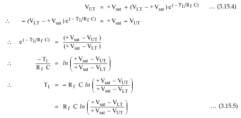
The
time taken by capacitor to charge from VUT to VLT is same
as time required for charging capacitor from VLT to VUT.
Therefore, total time required for one oscillation is given as
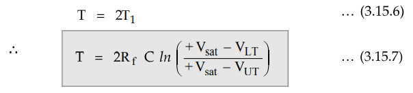
The
frequency of oscillation can be determined as fo = 1/T, where T
represents the time required for one oscillation.
Substituting
the values of T we get,
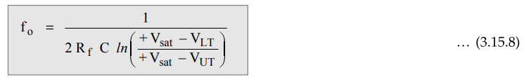
Substituting
the values of VUT and VLT we get,
2. Non-symmetrical Square Wave Generation
The
astable multivibrator can be used to obtain non-symmetrical square wave by
modifying the circuit as shown in the Fig. 3.15.3.
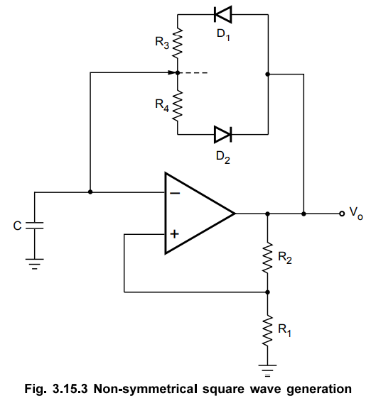
When
Vo = + Vsat, the C will charge through R3 due
to forward biasing of D1. When Vo = - Vsat, the
C will discharge R4 due to forward biasing of D2.
Selecting different values of R3 and R4, charging and
discharging time of C can be varied and hence nonsymmetrical square wave can be
obtained.
Variable
duty cycle : To vary duty cycle from say d1
% and d2 % then divide R3 + R4 resistance in
the ratio of the variable duty cycle required.
For
example if it is to be varied from 30 % to 70 % then divide R3 + R4
in the ratio 3 : 4 : 3 a shown in the Fig. 3.15.4.
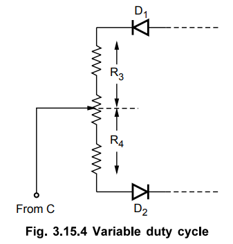
For
varying duty cycle from 10 % to 90 %, R3 + R4 to be divided
in the ratio 1:8:1 and so on.
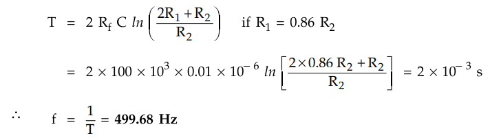
Example
3.15.1 In the square wave oscillator shown, calculate
the frequency of oscillations if R2 = 10 kΩ, R1 = 8.6 kΩ,
Rf = 100 and C = 0.01 µF.
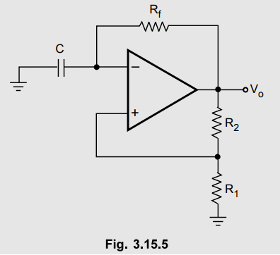
Solution : This is astable multivibrator using op-amp. Its time period is given by,
Review Question
1. Draw the circuit of an astable multivibrator using operational amplifier and derive an expression for its frequency of oscillation.
Linear Integrated Circuits: Unit III: Applications of Op-amp : Tag: : Working Principle, Pulse, Circuit Diagram, Solved Example Problems | Operational amplifier - Astable Multivibrator using Op-amp
Related Topics
Related Subjects

Linear Integrated Circuits
EE3402 Lic Operational Amplifiers 4th Semester EEE Dept | 2021 Regulation | 4th Semester EEE Dept 2021 Regulation