Electrical Machines: Unit V: Autotransformer and Three Phase Transformer
Autotransformer
Construction, Transformation Ratio, Power Transfer, VA Rating, Advantages, Limitations, Applications, Equivalent Circuit, Solved Example Problems
• Uptill now the two winding transformers are discussed in which the windings are electrically isolated and the e.m.f. in secondary gets induced due to induction. In practice, it is possible to use only one winding for the transformer so that part of this winding is common to the primary and secondary.
Autotransformer
AU: Dec.-03, 04, 05, 06, 07, 11,
14, 15, May-04, 05, 10
•
Uptill now the two winding transformers are discussed in which the windings are
electrically isolated and the e.m.f. in secondary gets induced due to
induction. In practice, it is possible to use only one winding for the
transformer so that part of this winding is common to the primary and
secondary. Such a special type of transformer having only one winding such that
part of the winding is common to the primary and secondary is called
autotransformer. Obviously the two windings are electrically connected and it
works on the principle of conduction as well as induction. Such an
autotransformer is very much economical where the voltage ratio is less than 2
and the electrical isolation of the two windings is not necessary. The power
transfer in 2 winding transformer is fully inductively while in autotransformer
the power is transferred from primary to secondary by both inductively as well
as conductively.
1. Construction of Autotransformers
•
In an autotransformer only one winding
is wound on a laminated magnetic core while in 2 winding transformer, two
windings are wound. The single winding of the autotransformer is used as
primary and secondary. The part of the winding is common to both primary and
secondary. The voltage can be stepped down or stepped up using an
autotransformer. Accordingly the autotransformers are classified as step up
autotransformer and step down autotransformer.
•
The Fig. 7.1.1 (a) shows the conventional two winding transformer while the
Fig. 7.1.1 (b) and (c) show the step down and step up autotransformers tep down
and st respectively.
.
•
In step down autotransformer shown in the Fig. 7.1.1 (b), the entire winding
acts as a primary while the part of the winding is used common to both primary
and secondary. Thus AB forms the primary having N1 turns while BC
forms the secondary with N2 turns. As N2 < N1,
the output voltage V2 < V1 and it acts as a step down
autotransformer. In step up autotransformer shown in the Fig. 7.1.1 (c), the
entire winding acts as secondary while the part of the winding is used common
to both primary and secondary. Thus AB forms the secondary having N2
turns while BC forms the primary with N1 turns. As N2
> N1, the output voltage V2 > V1 and it
acts as a step up autotransformer.

•
The current distribution in the step
down and step up autotransformers is shown in the Fig. 7.1.2 (a) and (b)
respectively.

2. Transformation
Ratio of an Autotransformer
•
Neglecting the losses, the leakage reactance and the magnetising current, the
transformation ratio of an autotransformer can be obtained as,
K= V2 / V1 = I1 /
I2 = N2 / N1
•
K is greater than unity for step up autotransformer while K is less than unity
for step down autotransformer.
•
Due to the use of single winding, compared to the normal two winding
transformer, for the same capacity and voltage ratio, there is substantial
saving in copper in case of autotransformers.
•
Let us obtain the expression for the copper saving in the autotransformers.
3. Copper Saving in Autotransformer
For
any winding, the cross-section of winding is proportional to the current I.
While the total length of the winding is proportional to the number of turns N.
Hence the weight of copper is proportional to the product of N and I.
Weight
of copper ∞ NI
where
I = Current in the winding
and
N = Number of turns of the winding
•
Consider a two winding transformer and step down autotransformer as shown in
the Fig. 7.1.3. (a) and (b).

Let
WTW = Total weight of copper in two winding transformer
WAT
= Weight of copper in autotransformer
In
two winding transformer,
Weight
of copper of primary ∞ N1 I1

Thus
saving copper is K times the total weight of copper in two winding transformer.
And
Saving of copper = (1/K) WTW …. For step pu autotransformer
Key Point: As the transformation ratio increases, the saving in copper is more and more.
4. Power Transfer in
Autotransformer
It
is mentioned earlier that the power input to an autotransformer gets
transferred to the secondary by two ways i.e.
1.
By electromagnetic induction i.e. inductively
2.
By conduction i.e. directly as windings are electrically connected.
Consider
a loaded autotransformer shown in the Fig. 7.1.4.

The
current drawn from the supply is I, while the input voltage is V1.
Input
power = V1 I1
While
the load current is I2 at a load voltage V2.
Output power = V2 I2
Now
BC portion has N2 turns and acts as secondary. The current induced
in this secondary due to transformer action is I2 – I1
while secondary induced voltage is V2.
Pt =
Power transformed inductively i.e. transformer action

While
the remaining power which is (K × Input power) gets transferred directly i.e.
conductively as windings are electrically connected.
Pt
= Power transformed = (1 - K) × Input
power
and
Pc = Power conducted through = K × Input power
Pc
= (Load power output) - Pt
Key Point:
Thus for the same excitation voltage and winding currents, the autotransformer
gives more output than two winding transformer. Hence autotransformer has
higher efficiency.
5. VA Rating of
Autotransformer
•
Let us compare the VA rating of two winding transformer and the VA rating of
two winding transformer when connected as an autotransformer.
•
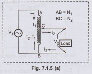
Consider an autotransformer connected to the load as shown in the Fig. 7.1.5
(a).
•
For the autotransformer the transformation ratio, neglecting the losses is,
K
= V2 / V1 = I1 / I2 = N2
/ N1
•
The VA rating of autotransformer is,
(VA)AT
= V1 I1 = V2 12
•
If the same transformer is used as a two winding transformer with AC as primary
and BC as secondary then its VA rating can be obtained as,

•
This is step down autotransformer with K < 1. So (1 – K) < 1 and we get
(VA)AT > (VA) TW.
•
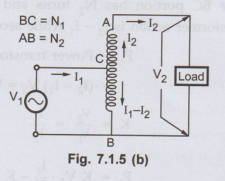
Now consider the step up autotransformer as shown in the Fig. 7.1.5 (b).
•
For the autotransformer, the ratio remains same as,
K
= V2 / V1 = I1 / I2
•
Hence VA rating of autotransformer is same as,
(VA)AT
+ V1 I1 = V2 I2
•
If the same transformer is used as two winding transformer then BC acts as
primary with current I1 – I2 while AB acts as secondary.
•
Hence its VA rating is,

Key Point:
So whether autotransformer is step up or step down, its VA rating is always
more than the corresponding two winding version.
So
the VA transferred in autotransformer, from primary to secondary is more as it
is due to both conduction and induction.
6. Conversion of Two Winding Transformer to an Autotransformer
• Consider a two winding transformer with the polarities as shown in the Fig. 7.1.6.

• The transformer turns ratio is 1 : 1 and V2 = V1
400 V.
• This transformer can be converted to an autotransformer in two ways, i) Additive polarity ii) Subtractive polarity.
a. Additive Polarity
•
The primary and secondary windings can b connected in series with additive
polarity, as shown in the Fig. 7.1.7.

•
The common point A which is common to inpu and output can be taken as the top of
autotransformer. The corresponding autotransforme is shown in the Fig. 7.1.8.

•
Thus if input is V1 then the output is V1 + V2
due to additive polarities.
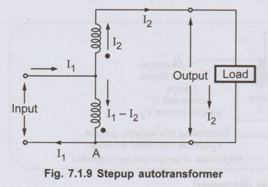
•
With common point A at the bottom autotransformer can be shown as in the Fig.
7.1.9.
b. Subtractive Polarity
•
The primary and secondary windings can be connected in series opposition as
shown in the Fig. 7.1.10 (a) which is called subtractive polarity.

•The
common point A which is common to input and output can be taken as the top of
the autotransformer as shown in the Fig. 7.1.10 (b).

Thus
if input is V1 then the output voltage is V1-V2
due to subtractive polarities.
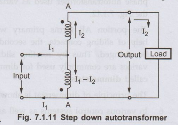
•
With common point A at the bottom, autotransformer can be shown as in the Fig.
7.1.11. A
7. Advantages of
Autotransformer
•
The various advantages of an autotransformer are,
1.
Copper required is very less.
2.
The efficiency is higher compared to two winding transformer.
3.
The size and hence cost is less compared to two winding transformer.
4.
The resistance and leakage reactance is less compared to two winding
transformer.
5.
The copper losses I2R, are less.
6.
Due to less resistance and leakage reactance, the voltage regulation is
superior than the two winding transformer.
7.
VA rating is more compared to two winding version.
8.
A smooth and continuous variation of voltage is possible.
8. Limitations of Autotransformer
•
Apart from its advantages, an autotransformer suffers from following
limitations,
1.
Low impedance hence high short circuit currents for short circuits on secondary
side.
2.
If a section of winding common to primary and secondary is opened, full primary
voltage appears across the secondary resulting in higher voltages on secondary
and danger of accidents.
3.
No electrical separation between primary and secondary which is risky in case
of high voltage levels.
4.
Economical only where the voltage ratio is less than 2.
9. Applications of
Autotransformer
•
The various applications of an autotransformer are,
1.
For safely starting the machines like induction motors, synchronous motors i.e.
as a startor.
2.
To give a small boost to a distribution cable to compensate for a voltage drop
i.e. as a booster.
3.
As a furnace transformer to supply power to the furnaces at the required supply
voltage.
4.
For interconnecting the systems which are operating roughly at same voltage
level.
5.
It can be used to vary the voltage to the load, smoothly from zero to the rated
voltage. Such a device giving smooth and continuous supply using an
autotransformer is called variac. A single phase autotransformer used as variac
is shown in the Fig. 7.1.12.

The
portion AB forms primary while with the help of sliding contacts, the secondary
turns can bag be changed. Thus by rotating sliding contact smooth variable
voltage can be obtained. Such variacs are commonly used for dimming the lights
in the cinema halls. Hence the variacs are also called dimmerstats.
The
principle of dimmerstat is shown in the Fig. 7.1.13.

6.
In various control systems as well as appliances.
10. Comparison with
Two Winding Transformer

11. Equivalent Circuit of Autotransformer
•
Consider an autotransformer as shown in the Fig. 7.1.14.
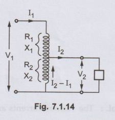
•
R1 and X1 are the resistance and inductance of that part
of the winding which carries only current I1.
•
R2 and X2 are the resistance and inductance of that part
of the winding which behaves as secondary.
•
Applying Kirchhoff's law,
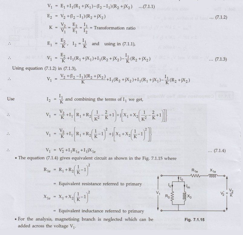
•
For the analysis, magnetising branch is neglected which can be added across the
voltage V1.
Ex. 7.1.1
The Fig. 7.1.16 shows an autotransformer
used to supply a load of 2 kW at 230 V from a 400 V a.c. supply. Find the
currents in parts AC and BC, neglecting losses and no load current. Also find
the copper saving due to the use of autotransformer instead of using two
winding transformer. Assume purely resistive load.
Sol. :

Ex. 7.1.2 A 10 kVA, 230/110 V transformer is
to be used as an autotransformer. What will be the voltage ratio and output
rating of an autotransformer ?
Solution:
The given values are,
Two
winding transformer = 230/110 V
kVA
rating = 10 kVA

•
Now as secondary voltage of two winding transformer is 110 V, let us assume
that autotransformer output voltage required is 110 V. So it can be connected
as an autotransformer as shown in the Fig. 7.1.17.

•
The part AC is primary of two winding while BC is secondary of two winding
transformer.
•
Thus for an autotransformer,

Note:
The problem may be solved by assuming output voltage required from an
autotransformer as 230 V in which case also the input voltage is 110 + 230 = 340
V. In such case we get voltage ratio as 23/24 and output rating as 30.909 kVA.
Students are expected to solve this case.
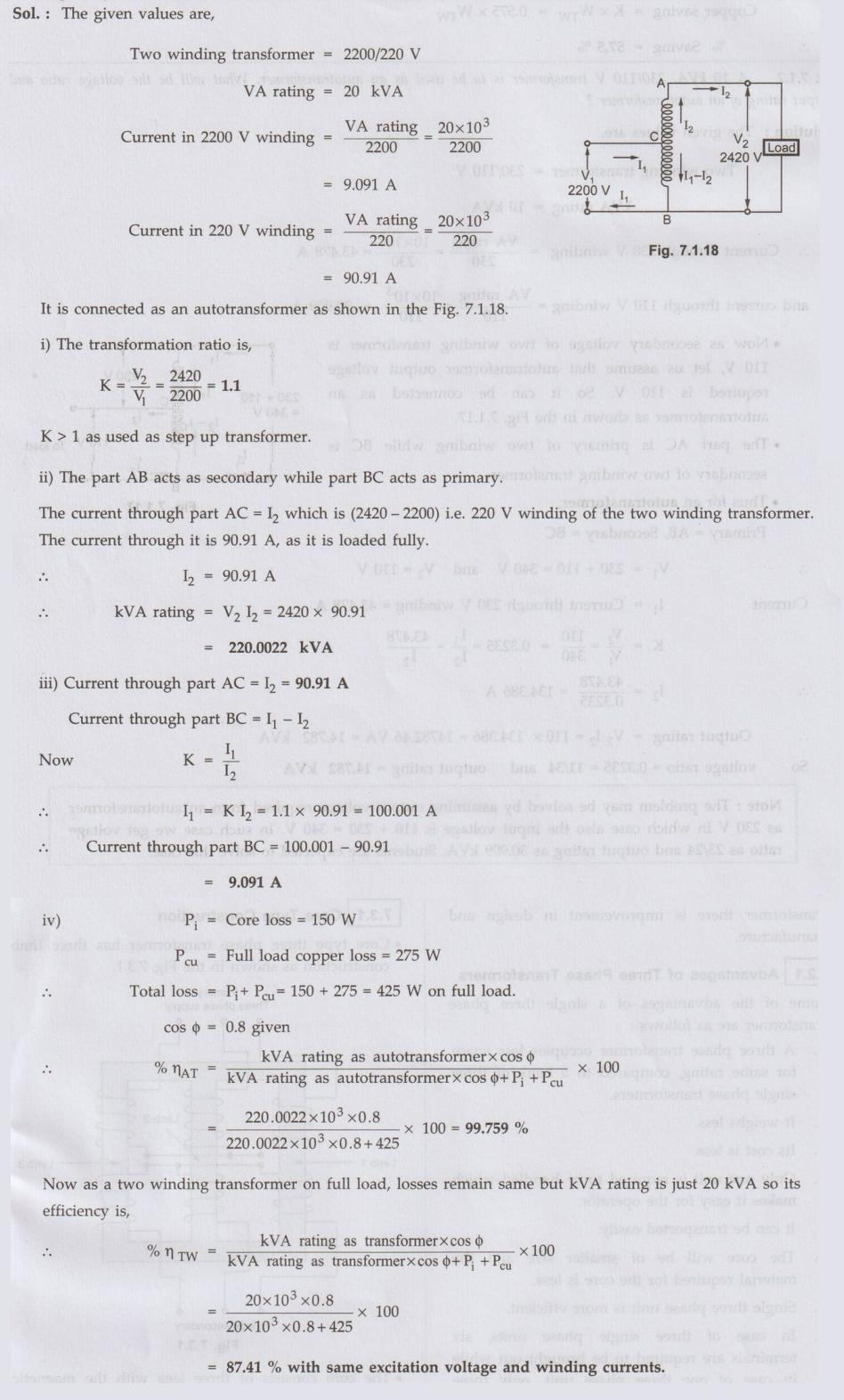
Ex. 7.1.3
A 2200/220 V, 20 kVA, two winding
transformer is connected as an autotransformer to transform 2200 V to 2420 V.
Find:
i) The transformation ratio of
autotransformer
ii) The kVA rating of
autotransformer
iii) The currents in various parts
of winding
iv) The efficiency at full load,
0.8 p.f. if the core loss is 150 W and full load copper loss 275 W. Compare it
with the two winding transformer.
Sol. :
Review Questions
1. Draw the circuit
and explain the principle of an autotransformer. Also derive the expression for
the volume of copper of an autotransformer. AU: Dec.-03, 04, 05, 06, 11, Marks 10
2. Explain the
working principle of autotransformer. AU May-04, 05, Dec.-05, Marks 6
3. Explain how two
winding transformer can be connected in autotransformer mode. AU: Dec.-07, Marks 4
4. Prove that the
amount of copper saved in autotransformer is (1- K) times that of ordinary
transformer. AU May-10, Dec.-14, Marks 6
5. Derive the expression for saving of copper in
autotransformer. AU:Dec.-15, Marks 6
6. State the
advantages and limitations of an autotransformer.
7. State the various
applications of an autotransformer.
8. A 10 kVA, 230/110
V transformer is to be used as an autotransformer. What will be the voltage
ratio and output rating of an autotransformer. [Ans.: 11/34, 14.782 KVA]
Electrical Machines: Unit V: Autotransformer and Three Phase Transformer : Tag: : Construction, Transformation Ratio, Power Transfer, VA Rating, Advantages, Limitations, Applications, Equivalent Circuit, Solved Example Problems - Autotransformer
Related Topics
Related Subjects

Electrical Machines I
EE3303 EM 1 3rd Semester EEE Dept | 2021 Regulation | 3rd Semester EEE Dept 2021 Regulation