Electrical Machines II: UNIT II: Synchronous Motor
Behaviour of Synchronous Motor on Loading
When a d.c. motor or an induction motor is loaded, the speed of the motor drops. This is because the load torque demand increases than the torque produced by the motor.
Behaviour of Synchronous Motor on Loading
When
a d.c. motor or an induction motor is loaded, the speed of the motor drops.
This is because the load torque demand increases than the torque produced by
the motor. Hence motor draws more current to produce more torque to satisfy the
load but its speed reduces. In case of synchronous motor speed always remains constant
equal to the synchronous speed, irrespective of load condition. It is
interesting to study how synchronous motor reacts to changes in the load
condition.
In
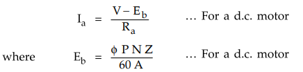
a d.c. motor, armature develops an e.m.f. after motoring action starts which
opposes supply voltage, called back e.m.f. Eb.
Hence
if Ra is the armature resistance and V is the supply voltage, we
have established the relation for the armature current Ia as,
In
case of synchronous motor also, once rotor starts rotating at synchronous
speed, the stationary stator (armature) conductors cut the flux produced by
rotor. The only difference is conductors are stationary and flux is rotating.
Due to this there is an induced e.m.f. in the stator which according to Lenz's
law opposes the supply voltage. This induced e.m.f. is called back e.m.f.
in case of synchronous motor. It is denoted as Ebpb i.e. back e.m.f. per phase.
This gets generated as the principle of alternator and hence alternating in
nature and its magnitude can be calculated by the equation,
Ebph
= 4.44 Kc Kd ϕ f Tph
or
Ebph oc ϕ
As
speed is always synchronous, the frequency is constant and hence magnitude of
such back e.m.f. can be controlled by changing the flux ϕ produced by the
rotor.
Key Point So back e.mf. in case
of synchronous motor depends on the excitation given to the field winding and
not on the speed, as speed is always constant.
As
stator construction is similar to the armature of a three phase alternator, the
impedance of the stator is called synchronous impedance of synchronous motor
consisting of Ra as the stator winding resistance and Xs
as the synchronous reactance. All the values are generally expressed on per
phase basis.
Zs
= Ra + j Xs Ω per phase
So
similar to the d.c. motor, we can write voltage equation for a synchronous
motor as,
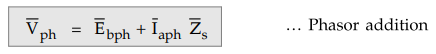
The
difference is that this equation is vector equation as each quantity is
alternating and has different phase. So addition is to be performed vectorially
to obtain the result.
where
Vph is the supply voltage per phase. The magnitude of Ebph is
adjusted almost equal to Vpb, on no load by controlling flux
produced by rotor i.e. field winding.
1. Ideal Condition on No Load
The
ideal condition on no load can be assumed by neglecting various losses in the
motor.
And
Vph = Ebph
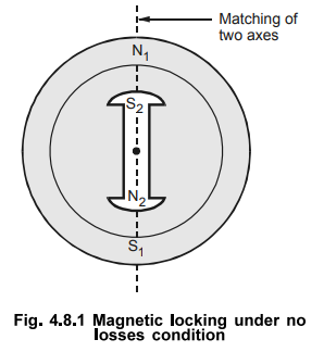
Under
this condition, the magnetic locking between stator and rotor is in such a way
that the magnetic axes of both, coincide with each other as shown in the Fig.
4.8.1. As this is possible only under no losses condition, is said to be ideal
in case of synchronous motor.
As
magnitude of Ebph and Vpb is same and Ebph opposes Vph, the phasor diagram for
this condition can be shown as in the Fig. 4.8.2.
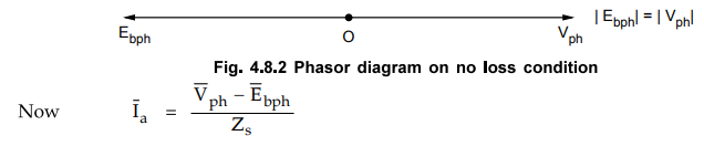
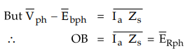
But
the vector difference 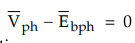 as seen from the phasor
diagram. Hence Ia = 0 under no losses condition.
as seen from the phasor
diagram. Hence Ia = 0 under no losses condition.
In
practice this is impossible. Motor has to supply mechanical losses and iron
losses alongwith small copper losses. To produce torque to overcome these
losses, motor draws a current from the supply. Let us see how it can be
explained in case of synchronous motor.
2. Synchronous Motor on No Load (With Losses)
We
have seen that Ebph and Vpb are magnitudewise same, which is adjusted by
controlling field current, in turn controlling the flux.
Now
due to the various losses practically present on no load, the magnetic locking
exists between stator and rotor but in such a way that there exists a small
angle difference between the axes of two magnetic fields as shown in the Fig.
4.8.3.
So
the rotor axis falls back with respect to stator axis by angle as shown in Fig.
4.8.3. This angle decides the amount of current required to produce the torque
to supply various losses.
Hence
this angle is called load angle, power angle, coupling angle, torque angle or
angle of retardation and denoted as δ as mentioned earlier.
The
magnetic locking still exists between the two and rotor rotates at synchronous
speed alongwith rotating magnetic field maintaining angle difference between
the axes of two field, as shown in the Fig. 4.8.3 (b). The flux lines between
the two get stretched due to such retardation of rotor axis with respect to
stator.
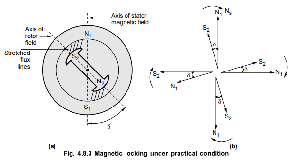
Now
though | Ebph | = | Vph |, Ebph will not be
located in exact opposition with Vpb, but will get displaced from its
initial position by angle 'δ' as shown in the Fig. 4.8.4.
Hence
the vector difference between the two, Ebpb and Vpb is not zero but give rise
to a phasor 'OB' as shown.
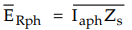
This
is called resultant phasor denoted as ![]() which is the product of
armature current per phase and armature impedance per phase.
which is the product of
armature current per phase and armature impedance per phase.
This
resultant decides the amount of current Iaph to be drawn to produce
the torque which meets the various losses present in the synchronous motor.
Under no load condition, δ is very small and hence ERpb is also very
small.
So
current drawn by the motor is also very small on no load which is the case in
all the various types of motors.
3. Synchronous Motor on Load
As
the load on the synchronous motor increases, there is no change in its speed.
But what gets affected is the load angle δ ’ i.e. the angle by which rotor axis
retards with respect to stator axis.
Hence
as load increases, 8 increases but speed remains synchronous.
As
δ increases, though Ebpb and Vpb magnitudes are same, displacement
of Ebpb from its ideal position increases. Hence the vector
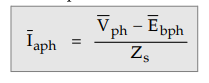
difference  increases. As
synchronous impedance is constant, the magnitude of Iapb drawn by
the motor increases as load increases. This current produces the necessary
torque which satisfies the increased load demand. The magnetic locking still
exists between the rotor and stator.
increases. As
synchronous impedance is constant, the magnitude of Iapb drawn by
the motor increases as load increases. This current produces the necessary
torque which satisfies the increased load demand. The magnetic locking still
exists between the rotor and stator.
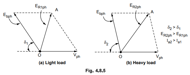
The
phasor diagrams showing ERpb increases as load increases are shown
in Fig. 4.8.5 (a) and (b).
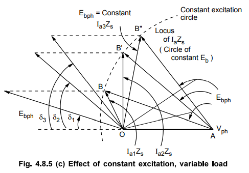
4. Constant Excitation Circle
As
Ebph depends on flux, for constant excitation Ebph is
constant. For constant excitation, if load is varied then δ keeps on changing,
due to which 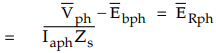 keeps on changing. The locus of extremities of
 is a circle and as Zs is
constant, represents current locus for the synchronous motor under constant
excitation and variable load conditions. As δ increases, Iaph Zs
increases and motor draws more current. As load decreases, δ decreases hence
Iaph Zs decreases and motor draws less current. Such a current locus
is shown in the Fig. 4.8.5 (c).
is a circle and as Zs is
constant, represents current locus for the synchronous motor under constant
excitation and variable load conditions. As δ increases, Iaph Zs
increases and motor draws more current. As load decreases, δ decreases hence
Iaph Zs decreases and motor draws less current. Such a current locus
is shown in the Fig. 4.8.5 (c).
So
from the above discussion it is clear that on no load, current drawn by the
motor is very small. This is because the stator and the rotor magnetic axes are
almost matching each other i.e. load angle δ is very small. As load increases,
rotor magnetic axis starts retarding with respect to stator axis i.e. load
angle δ increases maintaining the magnetic locking condition. And hence in case
of the synchronous motor load affects the angle 'δ' without affecting the
speed. As δ increases, the magnitude of ERph increases which shows
that motor draws more current from the supply. This satisfies the increased
load torque demand.
The
mechanical power developed by the synchronous motor is given by,
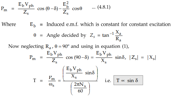
Key Point So torque produced
in the synchronous motor depends on the load angle '8' for small values of 8
and to be precise depends on 'sin 8'. The load angle '8' is measured in degrees
electrical.
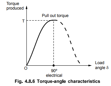
As angle δ increases, the magnetic flux lines producing the force of attraction between the two get more and more stretched. This weakens the force maintaining the magnetic locking, though torque produced by the motor increases. As 8 reaches upto 90° electrical i.e. half a pole pitch, the stretched flux lines get broken and hence magnetic locking between the stator and rotor no longer exists. The motor comes out of synchronism. So torque produced at ’ δ ’ equal to 90° electrical is the maximum torque, a synchronous motor can produce, maintaining magnetic locking i.e. synchronism. Such a torque is called pull out torque. The relationship between torque produced and load angle 8 is shown in the Fig. 4.8.6.
5. Synchronous Motor Connected to Infinite Bus Bar
The
synchronous motor connected to an infinite bus bar behaves similarly for the
changes in the load at constant excitation. As the load increases, the load
angle increases, current increases and power factor changes. The changes in the
power factor depends on the excitation used for synchronous motor i.e. whether
it is normally excited (Ebph = VpJ, over excited (Ebph > Vph),
or under excited (Ebph < Vph)
Thus
effect of change in load on synchronous motor connected to an infinite bus bar
can be summarized as,
1.
Irrespective of excitation, as load increases, the load angle δ and armature
current Ia increases.
2.
When the motor is normally excited (Ebph = Vph), then as load
increases, the change in current is more significant than the change in power
factor. The power factor tends to become more and more lagging as the load
increases.
3.
When the motor is over excited or under excited, the power factor changes are
more significant than the changes in the current as load changes.
4.
When the motor is over excited or under excited, the power factor tends to
approach to unity as the load increases.
6. Torques in Synchronous Motor
The
different torques in synchronous motor are,
1)
Starting torque : This is the torque developed by the
synchronous motor at start when rated voltage is applied to the stator. It is
also called breakaway torque. It is necessary to overcome friction and
inertia.
2)
Running torque : It is the torque developed by the motor
under running conditions. It is decided by the output rating of the motor and
speed of the driven machine.
3)
Pull in torque : Initially synchronous motor is rotated
at a speed slightly less than the synchronous speed. When speed is near to
synchronous, excitation is switched on and motor gets pulled into synchronism
and starts rotating at the synchronous speed. The amount of torque developed by
the motor at the time of pulling into synchronism is called pull in torque.
4)
Pull out torque : When the synchronous motor is loaded,
the rotor falls back with respect to stator by an angle called load angle δ. As
δ increases, magnetic locking between stator and rotor decreases. At 8 = 90°,
the torque developed is maximum by the motor and magnetic locking is very weak.
Any further increase in the load pulls motor out of synchronism and motor
stops. Thus the maximum torque developed by the synchronous motor without
pulling out of synchronism is called pull out torque.
Review Questions
1. Explain the effect
of variable load with constant excitation on synchronous motor. AU : May-13,
Marks 6
2. Draw the torque-angle
characteristics of synchronous motor and define pull-in and pull-out torque.
3. Define the various
torques associated with the synchronous motor.
4. Describe in detail
about the effect of load change on load angle and power factor of a three phase
synchronous motor operating on infinite bus bar and constant ey
5. Explain the
constant excitation circles for synchronous motor.
Electrical Machines II: UNIT II: Synchronous Motor : Tag: Engineering Electrical Machines - II : - Behaviour of Synchronous Motor on Loading
Related Topics
Related Subjects

Electrical Machines II
EE3405 Machine 2 EM 2 4th Semester EEE Dept | 2021 Regulation | 4th Semester EEE Dept 2021 Regulation