Digital Logic Circuits: Unit III: (c) Shift Registers
Buffer and Controlled Buffer Register
Shift Registers
• A group of flip-flops can be used to store a word, which is called register.
Introduction
•
A group of flip-flops can be used to store a word, which is called register.
•
A flip-flop can store 1-bit information. So an n-bit register has a group of n
flip-flops and is capable of storing any binary information/number containing
n-bits.
1. Buffer Register
•
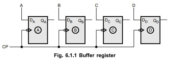
Fig. 6.1.1 shows the simplest register constructed with four D flip-flops. This
register is also called buffer register.
•
Each D flip-flop is triggered with a common negative edge clock pulse.
•
The input bits set up the flip-flops for loading.
•
When the first negative clock edge arrives, the stored binary information
becomes,
QAQBQCQD
= ABCD
•
In this register, four D flip-flops are used. So it can store 4-bit binary
information.
•
The number of flip-flop stages in a register determines its total storage
capacity.
2. Controlled Buffer Register
•
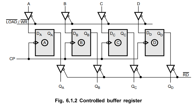
We can control input and output of the register by connecting tri-state devices
at the input and output sides of register as shown in Fig. 6.1.2. So this
register is called 'controlled buffer register 7.
•
Here, tri-state switches are used to control the operation.
•
When you want to store data in the register, you have to make  signal low to activate the tri-state buffers.
•
When you want the data at the output, you have to make ![]() signal low to
activate the buffers.
signal low to
activate the buffers.
• Controlled buffer registers are commonly used for temporary storage of data within a digital system.
•
As seen above the 4-bit register can store 4-bit binary information. In
general, n-bit register can store n-bit binary information.
Review Questions
1. What is register ?
2. What is buffer register ?
3. What do you mean by controlled buffer register ?
Digital Logic Circuits: Unit III: (c) Shift Registers : Tag: : Shift Registers - Buffer and Controlled Buffer Register
Related Topics
Related Subjects

Digital Logic Circuits
EE3302 3rd Semester EEE Dept | 2021 Regulation | 3rd Semester EEE Dept 2021 Regulation