Electrical Machines II: UNIT III: b. Circle Diagram
Calculation of Equivalent Circuit Parameters
Three Phase Induction Motor
Thus the resultant of parallel branches j X0 and (R2/s + j X2 )is almost equal to j X0.
Calculation of Equivalent Circuit Parameters
The
equivalent circuit of an induction motor is shown in the Fig. 6.6.1.
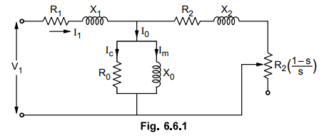
On
no load, slip is very very small hence R2/s is very large compared
to X0.
Thus
the resultant of parallel branches j X0 and (R2/s + j X2 )is almost equal to j X0 .Thus the equivalent circuit on no load is as shown in the Fig.6.6.2.
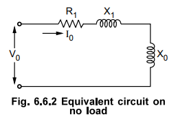
Xnl
= X1 + X0 = Stator self reactance … (6.6.1)
From
the no load readings,
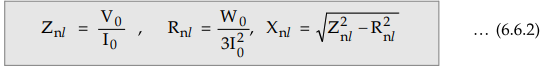
where
W0 = No load power input
If
stator resistance R1 is known then,
PR
= Rotational losses = Wo – Stator copper losses

Where
Io and R1 are per phase values.
The
blocked rotor test is like short circuit test on transformer. The equivalent
circuit for blocked rotor test is known in the Fig. 6.6.3. As rotor is still, s
= 1
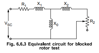
The
blocked rotor impedance as viewed through the stator terminals is given by,
Generally
X0 >> X2 hence X2 / X0 can be
neglected.
Xie
= X1 + X2
Generally
Xj is assumed equal to X2 as practically there is no method of
separating X1 and X2.
But Xnl = X1 + X0
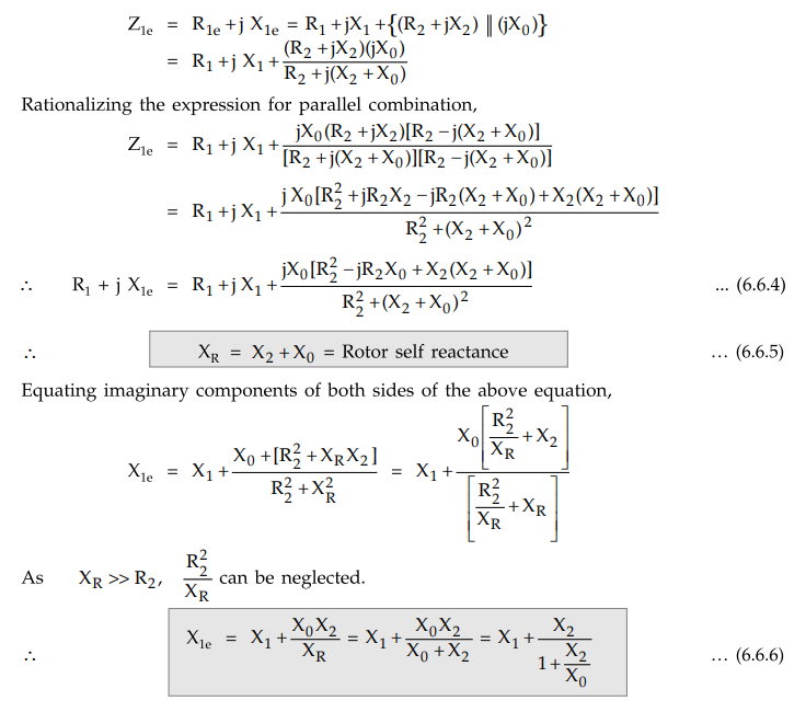
Equating
real parts of equation (6.6.4),
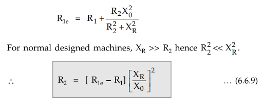
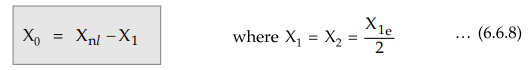
Hence
equation (6.6.8) given X0, equation (6.6.9) gives R2
while R1 from d.c. resistance per phase of stator winding can be
obtained.
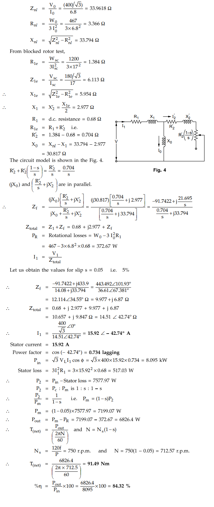
Example
6.6.1 The results of the no-load and blocked rotor
tests on a 3-phase, Y-connectedc 10 kW, 400 V, 17 A, 50 Hz. 8-pole induction
motor with a squirrel-cage rotor are given below.
No-load
test : Line-line voltage = 400 V
Total
input power = 467 W
Line
current = 6.8 A
Blocked
rotor tests : Line-line voltage = 180 V
Total
input power = 1200 W
Line
current = 17 A
The
d.c. resistance of the stator measured immediately after the blocked rotor test
is found to have an average value of 0.68 ohm.phase. Calculate the parameters
of the circuit model of the induction motor. Draw circuit model. Calculate : i)
Torque (net), ii) Stator current, iii) Power factor, iv) Efficiency.
Solution
:
From
no load test,
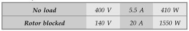
Example
6.6.2 A 3 phase, 400 V, 50 Hz star connected induction
motor gave the following test results :
The
ratio of standstill leakage reactance of stator and rotor is estimated as 2. If
the motor is running at a speed of 960 r.p.m. Determine,
i)
Net mechanical power output ii) Net torque iii) Efficiency of the motor.
Assume
stator and rotor copper losses to be equal.
Solution
:
On
no load, slip snl is very small hence R2 / snl in the
equivalent circuit is very large compared to Hence parallel combination of jXm,
and R2 / snl is almost equal to jXm

Example for Practice
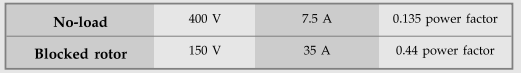
Example
6.6.3 The following test results were obtained on a
7.5 kW, 400 V, 4-pole, 50 Hz, delta connected induction motor with a stator
resistance of 2.1. ohm/phase.
Obtain
the approximate equivalent circuit model. Also estimate the breaking torque developed
when the motor running with a slip of 0.05 has two of its terminals suddenly
interchanged.
[Ans.:
0.5916 <Vph, 3.829 Ω, 390.233 Ω, 42.234 Ω, 1.2916 Ω, Tbreaking =
19.667 Nm]
Review Question
1. How do obtain equivalent circuit parameters from the no load
test and blocked rotor test on induction motor.
Electrical Machines II: UNIT III: b. Circle Diagram : Tag: Engineering Electrical Machines - II : Three Phase Induction Motor - Calculation of Equivalent Circuit Parameters
Related Topics
Related Subjects

Electrical Machines II
EE3405 Machine 2 EM 2 4th Semester EEE Dept | 2021 Regulation | 4th Semester EEE Dept 2021 Regulation