Electrical Machines II: UNIT V: a. Single Phase Induction Motors
Capacitor Start Induction Motors
Circuit, Phasor diagram, Operation Working Principle, Applications, Example Solved Problems | Single Phase Induction Motors
Depending upon whether capacitor remains in the circuit permanently or is disconnected from the circuit using centrifugal switch, these motors are classified as, 1. Capacitor start motors 2. Capacitor start capacitor rim motors
Capacitor Start Induction Motors AU
: May-04,08,12,13,16,18, Dec.-06,ll,13
The
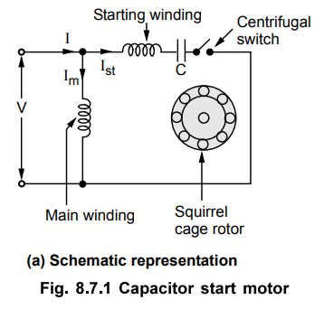
construction of this type of motor is similar to the resistance split phase
type. The difference is that in series with the auxiliary winding the capacitor
is connected. The capacitive circuit draws a leading current, this feature used
in this type to increase the split phase angle a between the two currents Im
and Ist.
Depending
upon whether capacitor remains in the circuit permanently or is disconnected
from the circuit using centrifugal switch, these motors are classified as,
1.
Capacitor start motors 2. Capacitor start capacitor rim motors
The
construction of capacitor start motor is shown in the Fig. 8.7.1 (a).
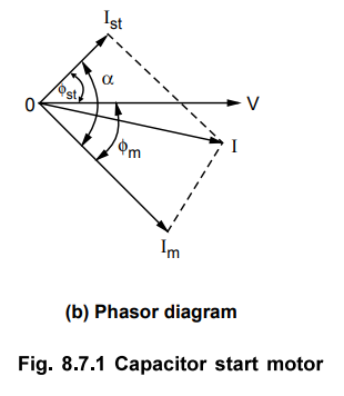
The
current Im lags the voltage by angle m while due to capacitor the current Ist
leads the voltage by angle st. Hence there exists a large phase difference
between the two currents which is almost 90°, which is an ideal case. The
phasor diagram is shown in the Fig. 8.7.1 (b).
The
starting torque is proportional to 'a' and hence such motors produce very high
starting torque.
When
speed approaches to 75 to 80 % of the synchronous speed, the starting winding
gets disconnected due to operation of the centrifugal switch. The capacitor
remains in the circuit only at start hence it is called capacitor start motors.
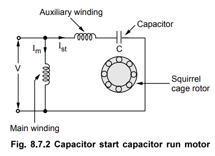
In case of capacitor start capacitor run motor, there is no centrifugal switch and capacitor remain parmanently in the circuit. This improves the power factor. The schematic representation of such motor is shown in the Fig. 8.7.2.
The
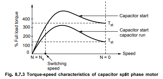
phasor diagram remains same as shown in the Fig. 8.7.2 (b). The performance not
only at start but in running condition also depends on the capacitor C hence
its value is to be designed so as to compromise between best starting and best
running condition. Hence the starting torque available in such type of motor is
about 50 to 100 % of full load torque. The torque-slip characteristics is shown
in the Fig. 8.7.3.
The
direction of rotation, in both the types can be changed by interchanging the
connections of main winding or auxiliary winding. The capacitor permanently in
the circuit improves the power factor. These motors are more costly than split
phase type motors.
The
capacitor value can be selected as per the requirement of starting torque, the
starting torque can be as high as 350 to 400 % of full load torque. The
torque-speed characteristics is as shown in the Fig. 8.7.3.
1. Applications
These
motors have high starting torque and hence are used for hard starting loads.
These are used for compressors, conveyors, grinders, fans, blowers,
refrigerators, air conditioners etc. These are most commonly used motors. The
capacitor start capacitor run motors are used in ceiling fans, blowers and
air-circulators. These motors are available upto 6 kW.
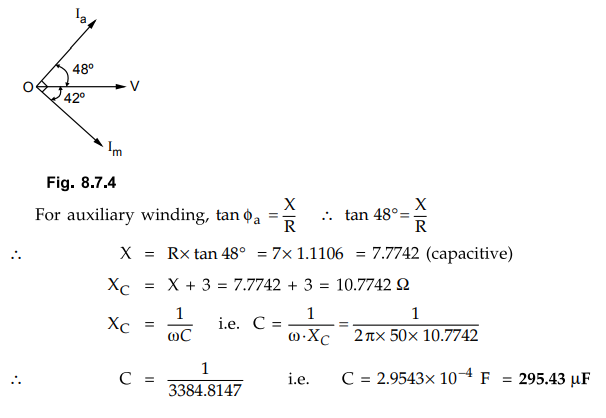
Example
8.7.1 The main and auxiliary winding impedances of a
50 Hz, capacitor start single phase induction motor are (3 + j 2.7) ohm and (7
+ j 3) ohm respectively. Determine the value of the capacitor to be connected
in series with the auxiliary winding to achieve a phase difference of 90°
between the currents of the two windings at start. AU : May-04, Marks 8
Solution
:
Let XC be the reactance of the capacitor connected in the auxiliary
winding.
Za
= 7 + j 3
Then
Za = 7 + j 3 - j XC = 7 - jX
Now
Zm = 3 + j 2.7 = 4.036 ∠42°Ω
Thus
Im lags behind V by 42°.
Since,
time phase angle between Im and Ia has to be 90°, 1, must lead V by,
90°-42°
= 48°
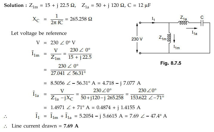
Example
8.7.2 The equivalent impedances of the main and
auxiliary windings in a capacitor motor are (15 + j 22.5) Ω and (50 + j
120) 2 respectively, while the capacitance of the capacitor is 12 uF. Determine
the line current at starting on a 230 V, 50 Hz supply. AU : May-13, Marks 8
Solution
:
Examples
for Practice
Example
8.7.3 The resistance and inductive reactance of each
winding of a 50 Hz single phase capacitor induction motor are 80 ohms and
237.58 ohms respectively. Additional resitance "R" and a capacitor
"C" are in series with one winding in order to achieve a phase
difference of 90 degrees while both windings carry equal current. Calculate the
values of R and C.
[Ans.:
R = 157.495 Ω, C = 10 µF]
Examples
8.7.4 A 250 watt, 230 V, 50 Hz, single phase capacitor
start Induction motor has the following constants for the main and auxiliary
windings. Main winding, Zm =(4.5 + j 3.7 ) Ω, awxz'Zza^ winding Za =(9.5
+ j 3.5) Ω. Determine the value of the capacitor that will place the
main and auxiliary winding currents in quadrature at starting.
[Ans.
: 211.40 µF]
Review Question
1. Describe the principle of operation of single phase induction
motor using capacitor. Draw the circuit and phasor diagram.
Electrical Machines II: UNIT V: a. Single Phase Induction Motors : Tag: Engineering Electrical Machines - II : Circuit, Phasor diagram, Operation Working Principle, Applications, Example Solved Problems | Single Phase Induction Motors - Capacitor Start Induction Motors
Related Topics
Related Subjects

Electrical Machines II
EE3405 Machine 2 EM 2 4th Semester EEE Dept | 2021 Regulation | 4th Semester EEE Dept 2021 Regulation