Microprocessors and Microcontrollers: Unit IV: (b) Programmable Interrupt Controller (PIC) - 8259
Cascading
Review Question : 1. Draw and explain the interfacing of cascaded 8259s with 8085.
Cascading
The
8259A can be easily interconnected to get multiple interrupts. Fig. 9.8.1 shows
how 8259A can be connected in the cascade mode. In cascade mode one 8259A is
configured in Master mode and other should be configured in the Slave mode. In
this figure, 8259A-1 is in the master mode and others are in slave mode. Each
slave 8259A is identified by the number which is assigned as a part of its
initialization. Since the 8085 has only one INTR input, only one of the 8259A
INT pins is connected to the 8085 INTR pin. The 8259A connected directly to the
8085 INTR pin is referred to as the master. The INT pins from other 8259As are
connected to the IR inputs of the master 8259A. These cascaded 8259As are
referred to as slave. The  signal is connected to both master and slave
8259A.
signal is connected to both master and slave
8259A.
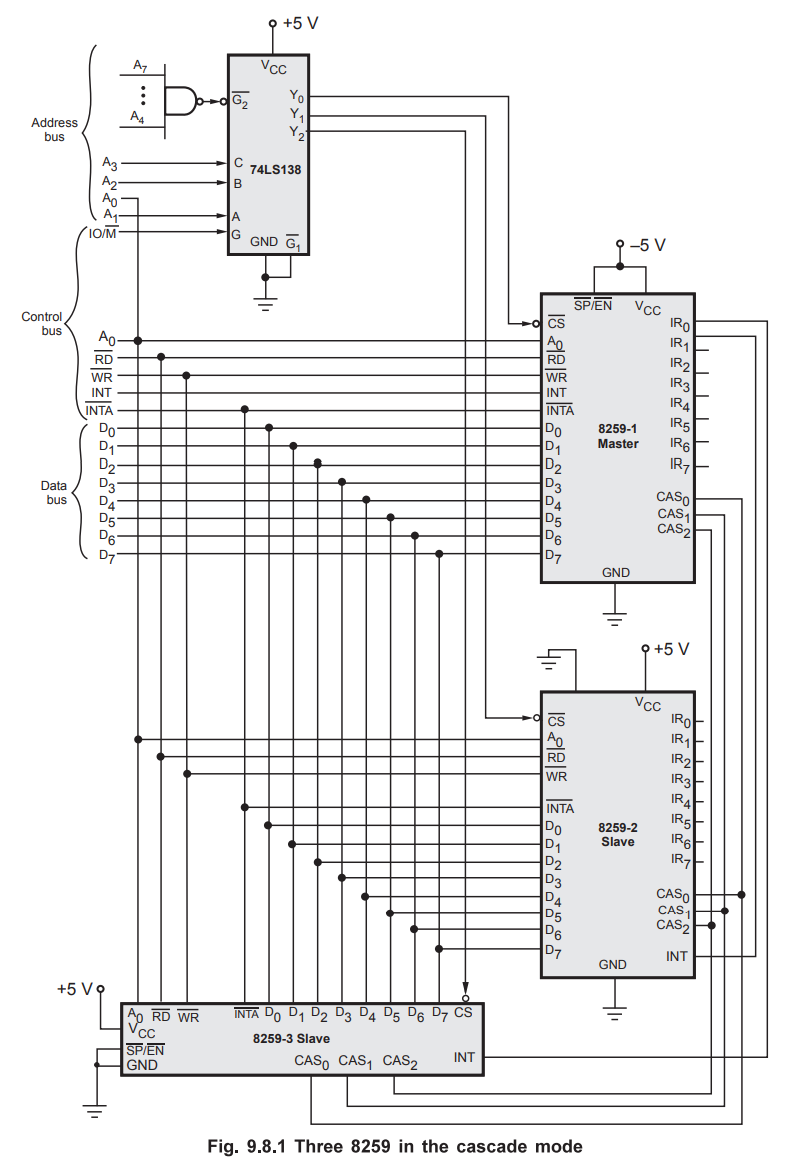
The
cascade pins CAS0 to CAS2 are connected from the master
to the corresponding pins of the slave. For the master these pins function as
outputs, and for the slave these pins function as inputs. The  signal
is tied high for the master. However, it is grounded for the slave.
signal
is tied high for the master. However, it is grounded for the slave.
Each 8259A has its own addresses so that command words can be written to it and status bytes read from it.
Addresses for 8259As:
 Master
and Slave Operation :
Master
and Slave Operation :
When
the slave receives an interrupt signal on one of its IR inputs, it checks mask
condition and priority of the interrupt request. If the interrupt is unmasked
and its priority is higher than any other interrupt level being serviced in the
slave, then the slave will send an INT signal to the IR input of a master. If
that IR input of the master is unmasked and if that input has higher priority
than any other IR inputs currently being serviced, then the master will send an
INT signal to the 8085 INTR input. If the INTR interrupt is enabled, the 8085
will go through its INTR interrupt procedure and sends three pulses
to both the master and the slave. In response to first interrupt acknowledge
signal opcode for CALL instruction is put on the data bus and the master
outputs a 3-bit slave identification number on the CAS0-CAS2
lines. Sending the 3-bit ID number enables the slave. When the slave receives
the second pulse from the 8085, the slave will send the low-order
address byte of the ISR on the data bus. Finally, slave sends the high-order
byte of the ISR on the data bus on receiving third signal.
If
an interrupt signal is applied directly to one of the IR inputs of the master,
the master will send the opcode for CALL instruction to the 8085 when it
receives the first pulse from the 8085. It then sends low-order byte
and high-order byte in successive interrupt acknowledge cycles (second and
third).
Review Question
1. Draw and explain the interfacing of cascaded 8259s with 8085.
Microprocessors and Microcontrollers: Unit IV: (b) Programmable Interrupt Controller (PIC) - 8259 : Tag: : - Cascading