Basic Civil & Mechanical Engineering: UNIT IV: f. Pumps
Centrifugal Pumps - Classification According to the type of casing
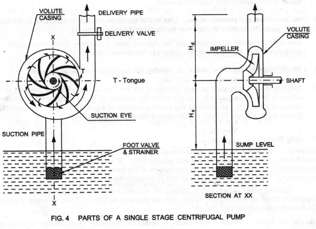
1. Volute Casing: The centrifugal pump has a stationary outer casing. It has an air-tight spiral passage surrounding the impeller. Hence, it is also known as Spiral Casing.
Classification
According To THE TYPE OF CASING
1. VOLUTE CASING
Description (Fig. 4]
1.
Volute Casing (Spiral Casing)
2.
Impeller
3. Suction Pipe with Strainer and Foot Valve
4.
Delivery Pipe and Delivery Valve
5. Shaft
6.
Stuffing Box
1. Volute Casing:
The centrifugal pump has a stationary outer casing. It has an air-tight spiral
passage surrounding the impeller. Hence, it is also known as Spiral Casing.
In
this casing, area of flow of liquid increases gradually. The increase in area
of flow decreases the velocity of flow. Consequently, the decrease in velocity
increases the pressure of the liquid flowing through the casing.
Tongue
(T): Note that the volute increases in area from its initial point, called
Tongue (T), until it covers the full 360° around the impeller and then joins
the outlet.
2.
Impeller: Impeller is the rotating part of the
centrifugal pump. It is mounted on a shaft. It consists of backward curved
vanes or blades.
Impellers may be classified as:
•
Closed Impeller: A Closed Impeller
has vanes with metal cover plates on both sides. These plates are known as
crown plate and lower or base plate. The closed impeller provides better
guidance for the liquid. It is more efficient. However, this type of impeller
is suited when the liquid to be pumped is pure.
•
Semi-Open Impeller: It has vanes
with base plate only and no crown plate. It is suitable even for liquids with
dirt.. Open Impeller: Its vanes have neither crown plate nor base plate. It is
useful for pumping liquids containing suspended solid matter such as sewage,
etc.
3. Suction Pipe with Strainer and
Foot Valve: Suction Pipe is connected at its upper
end to the inlet of the pump at the center of the impeller, i.e., at the Suction
Eye of the Impeller. The lower end of the suction pipe dips into liquid in a
sump from which the liquid is to be lifted up.
The
liquid from the sump enters the Strainer. The strainer filters impurities such
as leaves in liquid. The liquid then passes through Foot Valve to enter the
suction pipe.
Foot
valve is a non-return valve, i.e., one-way valve. It opens only in the upward
direction. Therefore, the liquid will pass through the foot valve upwards only.
It will not allow the liquid to flow downwards back to the sump.
4. Delivery Pipe and Delivery
Valve: One end of the Delivery Pipe is connected to the
outlet of the pump. The other end delivers the liquid at the required height.
Just near the outlet of the pump on the delivery pipe, a Delivery Valve is provided.
It controls the flow of liquid from the pump into the delivery pipe.
5. Shaft: Shaft
is coupled to motor. It transfers the torque from motor to impeller.
6. Stuffing Box:
It is used to stop leakage of air into the casing when the pressure in the casing
is below atmospheric. It also stops the leakage of liquid under pressure from
the casing of the pump. The stuffing box packing consists of a soft
semi-plastic material. This plastic material is cut in rings. It fits around
the shaft or shaft sleeve.
Working Principle
Priming:
The first step in the operation of a centrifugal pump is Priming. Priming means
removal of air from the pump casing and suction line. If an impeller is made to
rotate in the presence of even a small air packet in any portion of the pump,
only a negligible pressure would be produced. The result is that no liquid will
be lifted by the pump. .
Suction
pipe, casing and a portion of the delivery pipe upto the delivery valve is
completely filled up from outside source with the liquid to be lifted. After
the pump is primed, the delivery valve is still kept closed.
Starting
the Motor: Motor is now started to rotate the impeller. The
delivery valve is kept closed in order to reduce the starting torque for the
motor.
Vacuum
at the Suction Eye: As the impeller rotates inside the
casing, a centrifugal force is produced. A vacuum is created at the Suction Eye
of the impeller due to centrifugal action. This causes sucking of the liquid
from the sump, which is at atmospheric pressure. Liquid rushes through the
suction pipe to the eye of the impeller.
When
the delivery valve is opened, the liquid flows in an outward radial direction.
Kinetic
Energy to Potential Energy: While flowing through the spiral passage in the
casing, the pressure increases with reduction in velocity. Kinetic Energy of
the leaving liquid from the impeller is converted into potential energy. This
potential energy of the liquid gives a high pressure head to lift the liquid to
a higher level.
The
pressure head developed depends on the speed of the impeller and the angle of
impeller blades.
Tongue
(T): As the flow proceeds from the Tongue (T) to the delivery pipe, more and
more liquid is continuously added from the impeller.
a.
CAVITATION
Cavitation
is an undesirable phenomenon. It may occur in the flowing liquid inside the
suction pipe line of the centrifugal pump.
When
a liquid is subjected to a pressure lower than its vapour pressure, it boils.
Hence, vapour bubbles are produced. These bubbles collapse violently when
subjected to high pressure. If the collapse of the bubbles is nearer to a solid
surface, then due to localized pressures, noise and vibrations are produced.
This phenomenon eats away the metal where it occurs. It is known as Cavitation.
Adverse Effects of Cavitation
•
Metal surfaces are damaged and cavities are formed on them; hence called Cavitation.
•
Due to sudden collapse of vapour bubbles, noise and vibrations are produced.
• Due to the pitting action, the surface of
the impeller vanes becomes rough. The force exerted by the liquid on the
impeller vanes decreases. Therefore, the work done by the liquid (output horse
power) is less. This results in decrease in efficiency.
Precautions against Cavitation
The
following precautions should be taken against cavitation:
•
The pressure of the flowing liquid inside the casing should not be allowed to
fall below its vapour pressure.
•
Special materials such as stainless steel, etc., which are cavitation-resistant
should be used for the pump casing, impeller, etc.
•
Pump NPSH (Net Positive Suction Head)
In
order to avoid cavitation, the suction head of the pump has to be increased by
using a booster pump before the main pump. The suction head to be created to
avoid cavitation is known as Net Positive Suction Head (NPSH). NPSH has to be
increased at a rate greater than the square of the operating speed of the pump.
b.
TERMINOLOGY
•
Gauge Pressure
Gauge
Pressure is measured above atmospheric pressure, whereas absolute pressure
always refers to perfect vacuum as the datum point.
• Vacuum
It
is the depression of pressure below the atmospheric pressure. mercury. It is
expressed in mm of
• Static Head
The pressure at any point in liquid contained
in a vertical column of that liquid is caused by the weight of that liquid in
the column above the point in question. The height of the column of the liquid
is called Static Head, expressed in meters of the liquid.
• Suction Lift
Suction
Lift is defined as the vertical distance in meters from the liquid supply level
to the pump center line with the pump physically located above the liquid
supply level.
• Suction Head (Hs)
Suction Head is the vertical height of the
center line of the centrifugal pump above the liquid surface in the sump from
which liquid is to be lifted. It is denoted as Hs.
• Delivery Head (Hd)
Delivery Head is the vertical distance between
the center line of the pump and the liquid surface in the tank to which the
liquid is delivered. It is denoted as Hd.
• Capacity
Capacity is the discharge of the pump
expressed in gallons per minute (gpm), or cubic meters per hour.
• Efficiency of Centrifugal Pump
In a centrifugal pump, power is transmitted
from the shaft of the electric motor to the shaft of the pump and then to the
impeller. From the impeller, the power is given to the liquid. Thus, power is
decreasing from the shaft of the pump to the impeller and then to the liquid.
Mechanical
Efficiency: It is the ratio of the power available at the impeller to the power
at the shaft of the centrifugal pump.
Mechanical
Efficiency = Power at the impeller/ Power at the pump shaft
• Specific Speed of Centrifugal
Pump (Ns) A dimensionless index of pump known as Specific
Speed has been developed for pump design and selection to show the relationship
between pump capacity, head and impeller speed.
The
Specific Speed of a centrifugal pump is defined as the speed in revolutions per
minute at which a geometrically similar impeller would deliver one cubic meter
of liquid per second against a delivery head of one meter. It is denoted as Ns.
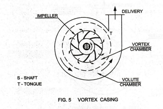
2. VORTEX CASING [Fig. 5]
Working Principle
Vortex
Chamber: The action of volute casing to convert the velocity
head of the liquid into pressure head can be improved. How? A parallel walled
circular chamber is inserted between the impeller and the volute casing. This
chamber is known as Vortex or Whirlpool Chamber as shown.
The
liquid leaving the impeller blades at a high pressure moves freely in this
vortex chamber. Its velocity head is gradually transformed into pressure head.
Afterwards, the liquid is flowing through volute chamber.
Volute Chamber: In the volute chamber,
pressure of the liquid is further increased. It is then discharged through the
delivery pipe.
High
Efficiency: The efficiency of the pump with vortex
casing is more than the efficiency when only volute casing is provided.
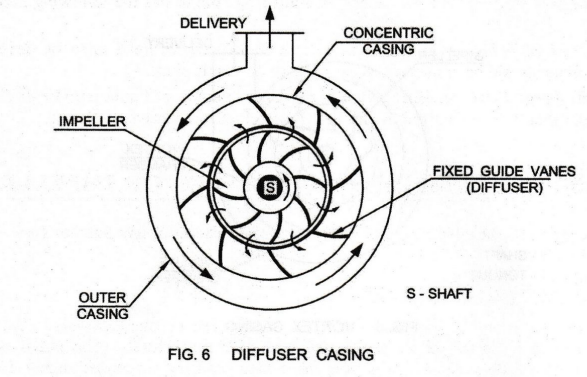
3. DIFFUSER CASING [Fig. 6]
Working Principle
Fixed Guide Vanes as Diffuser:
Impeller of this pump is surrounded by a Concentric Casing with fixed guide
vanes. The ring of fixed guide vanes is known as Diffuser.
The
high pressure liquid from the impeller enters the fixed guide vanes in full
without stock. In the guide vanes, the area of flow of liquid increases.
Therefore, the velocity of flow is reduced. Consequently, pressure of liquid
further increases. It then passes through the outer casing and is discharged
through the delivery pipe.
Highest Efficiency:
In a diffuser pump, the amount of conversion of velocity head into pressure
head is greater than with vortex casing. Hence, the efficiency is much greater
than in the case of a pump with simple volute casing. The diffuser type of pump
has, therefore, the highest efficiency.
It
may be noted that the fast moving liquid from the impeller can meet the fixed
guide vanes of the diffuser without shock, only when the pump is operating at
rated capacity. At part loads, the multiple vanes of the diffuser cause shock
and turbulence.
Uses: Due to the above disadvantage and due to improvements in the volute casing, both are equally efficient these days. Diffuser, however, still finds applications in multistage high pressure pumps.
Basic Civil & Mechanical Engineering: UNIT IV: f. Pumps : Tag: : - Centrifugal Pumps - Classification According to the type of casing
Related Topics
Related Subjects

Basic Civil and Mechanical Engineering
BE3255 2nd Semester 2021 Regulation | 2nd Semester EEE Dept 2021 Regulation