Electrical Machines: Unit II: D.C. Generators
Characteristics of Separately Excited D.C. Generators
The characteristics of separately excited d.c. generator are divided into two types, 1) Magnetisation and 2) Load characteristics.
Characteristics
of Separately Excited D.C. Generators
•
The characteristics of separately excited d.c. generator are divided into two
types,
1)
Magnetisation and 2) Load characteristics.
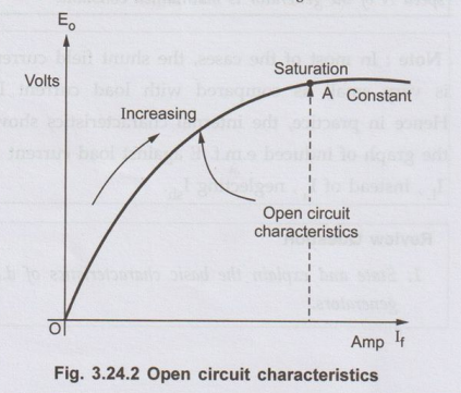
1. Magnetisation or Open Circuit Characteristics
The
arrangement to obtain this characteristics is shown in the Fig. 3.24.1.

•
The rheostat as a potential divider is used to control the field current and
the flux. It is varied from zero and is measured on ammeter connected.
Eo
= ϕ PNZ / 60 A
•
As I is varied, then changes and hence induced e.m.f. E also varies. It is
measured on voltmeter connected across armature. No load is connected to
machine, hence characteristics are also called no load characteristics which is
graph of E。
against field current I as shown in the Fig. 3.24.2. As If increases, flux
increases and Eo increases. After point A, saturation occurs when
becomes constant and hence Eo saturates.
2. Load Saturation Curve
•
This is the graph of terminal voltage Vt against field current If.
When generator is loaded, armature current Ia flows and armature
reaction exists. Due to this, terminal voltage Vt is less than the
no load rated voltage. On no load, current Ia is zero and armature
reaction is absent. Hence less number of ampere turns are required to produce
rated voltage Eo.
•
These ampere-turns are equal to OB as shown in the Fig. 3.24.3. On load,
to produce same voltage more field ampere-turns are required due to
demagnetising effect of armature reaction. These are equal to BC as shown in
the Fig. 3.24.3. Similarly there is drop Ia Ra across
armature resistance. Hence terminal voltage V = E - I Ra. This graph
OR is also shown in the Fig. 3.24.3. The triangle PQR is called drop reaction
triangle. Thus OP is no load saturation curve, OQ is the graph of generated
voltage on load and OR is the graph of terminal voltage on load.

3. Internal and External Characteristics
•
Let Eo be the no load rated voltage which drops to E due to armature
reaction on load and further drops to Vt due to armature resistance
drop Ia Ra on load.
•
The graph of Vt against load current IL is called
external characteristics while the graph of E against load current IL
is called internal characteristics.
These
are shown in the Fig. 3.24.4 for separately excited d.c. generator. The graphs
are to be plotted for constant field current. In case of separately excited
d.c. generator induced e.m.f. is totally dependent on flux ϕ i.e. field curent If. Hence to have
control over the field current, in case of separately excited d.c. generators
field regulator is necessary.

Review Question
1. Draw and explain
the charactreristics of seperately excited d.c. generators.
Electrical Machines: Unit II: D.C. Generators : Tag: : - Characteristics of Separately Excited D.C. Generators
Related Topics
Related Subjects

Electrical Machines I
EE3303 EM 1 3rd Semester EEE Dept | 2021 Regulation | 3rd Semester EEE Dept 2021 Regulation