Electrical Machines II: UNIT III: b. Circle Diagram
Circle Diagram for a Series R- L Circuit
It is excited by an alternating source of V volts. The frequency of the source is f Hz.
Circle Diagram for a Series R- L Circuit
Consider
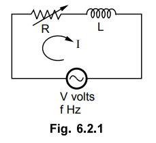
a series R-L circuit with a variable R as shown in the Fig. 6.2.1. It is
excited by an alternating source of V volts. The frequency of the source is f
Hz.
Let
I = current flowing through the circuit
Z
= Impendance of the circuit
Z
= R + j XL where XL = 2π fL
Now
R is variable while XL is fixed.
The
phasor diagram is shown in the Fig. 6.2.2 (a). The current I lags voltage V by
angle ϕ as the circuit is inductive. The impedance triangle is shown in the
Fig. 6.2.2 (b).
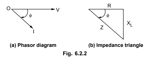
From
the impedance triangle we can write,
Sin
ϕ = XL / Z
Substituting
in the expression for I,
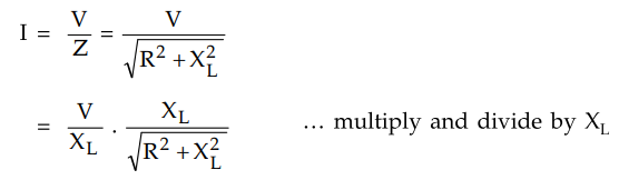
I
= [V/ XL ] sin ϕ … (6.2.1)
This
is the equation of a circle in polar co-ordinates with a diameter equal to (V/XL).
When
the resistance R = 0, then ϕ = 90° hence sin ϕ = 1.
I
= Im = V / XL
This
is the maximum value of current.
As
R increases, the phase angle ϕ decreases thus decreasing sin ϕ . Effectively
current I also decreases. When R → ∞ the ϕ → 0° and current becomes zero.
The
locus obtained of extremities of a current phasor plotted for various values of
R is a semicircle. The semicircle is shown in the Fig. 6.2.3.

The
voltage axis is taken as vertical axis as a reference, with respect to which
the various current phasors are plotted.
The
power factors at various conditions are cos ϕ1, cos ϕ2
etc. As varies only from 0° to 90°, the diagram is semicircle, infact it is a
half part of a circle hence it is known as circle diagram.
This
theory of series R-L circuit can be easily extended to a three phase induction
motor.
Electrical Machines II: UNIT III: b. Circle Diagram : Tag: Engineering Electrical Machines - II : - Circle Diagram for a Series R- L Circuit
Related Topics
Related Subjects

Electrical Machines II
EE3405 Machine 2 EM 2 4th Semester EEE Dept | 2021 Regulation | 4th Semester EEE Dept 2021 Regulation