Electrical Machines II: UNIT III: b. Circle Diagram
Circle Diagram of a 3 Phase Induction Motor
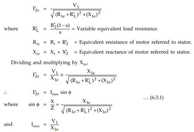
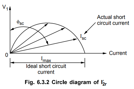
The I2r will be at its maximum when Rie + RL = 0 i-e., there exists an ideal short circuit. Hence current Imax is called ideal short circuit current of an induction motor.
Circle Diagram of a 3 Phase Induction Motor
The
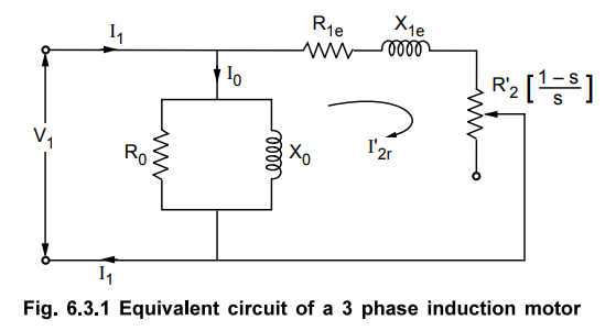
equivalent circuit of a 3 phase induction motor is shown in the Fig. 6.3.1.
All
the values shown are per phase values. The circuit is similar to a series R-L
circuit. The reactance Xle is fixed while the total resistance Rle
+ (R2 (1 - s) / s) is variable. This is because the slip s varies as
load varies. The voltage across the parallel exciting branch is V1.
Hence we can write the expression for the rotor current referred to stator as,
The
I2r will be at its maximum when Rie + RL = 0
i-e., there exists an ideal short circuit. Hence current Imax is called ideal
short circuit current of an induction motor.
The
equation (6.3.1) represents equation of a circle with Imax as its
diameter. Thus locus of extremity of I2r is a circle, as shown in the Fig.
6.3.2.
But
the total stator current Ix per phase is a vector addition of current Io and
I2r.
I1
= Io + I2r …
vector addition
For
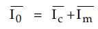
any induction motor, Io has a fixed value and phase angle 0 which is
decided by its active component Ic and magnetising component Im.
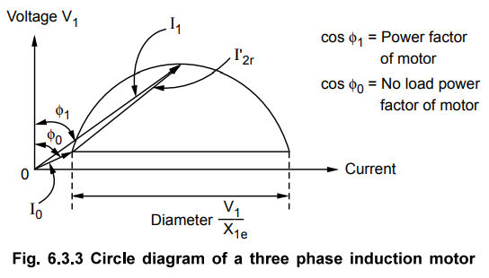
As
Io has fixed magnitude and phase, the locus of extremities of I1
which is Io + I2r is also a circle with a diameter still
as V1/Xle. The only change will be that the diameter V1/Xle
will no longer be along X-axis i.e. current axis but will get shifted at the
tip of the Io phasor. All the I2r phasors are to be drawn
from Io phasor to get I1 as Io has fixed
magnitude and phase angle ϕ0.
Thus
the current locus for a stator current I1 is also a semicircle which
is true called circle diagram of a three phase induction motor. This diagram
once obtained can be used to predict the performance of an induction motor
under variable load is shown in the Fig. 6.3.3.
Let
us see, how to obtain the data for plotting the circle diagram.
Review Question
1. Prove that the locus of extremity of current drawn by a three
phase induction motor under variable load conditions is a circle.
Electrical Machines II: UNIT III: b. Circle Diagram : Tag: Engineering Electrical Machines - II : - Circle Diagram of a 3 Phase Induction Motor
Related Topics
Related Subjects

Electrical Machines II
EE3405 Machine 2 EM 2 4th Semester EEE Dept | 2021 Regulation | 4th Semester EEE Dept 2021 Regulation