Electron Devices and Circuits: Unit V: (a) Feedback Amplifiers
Classification of Amplifiers
with Equivalent circuit
• Based on the magnitudes of the input and output impedances of an amplifier relative to the source and load impedances, respectively, we can classify amplifiers into four broad categories : Voltage, current, transconductance and transresistance amplifiers.
Classification of Amplifiers
AU
: Dec.-03, 04, May-05
•
Based on the magnitudes of the input and output impedances of an amplifier
relative to the source and load impedances, respectively, we can classify
amplifiers into four broad categories : Voltage, current, transconductance and
transresistance amplifiers.
1. Voltage Amplifier
•
Fig. 9.2.1 shows a Thevenin's equivalent circuit of an amplifier.

•
If the amplifier input resistance Ri is large compared with the
source resistance Rs then
Vi
≈ Vs
•
If the external load resistance RL is large compared with the output resistance
Ro of the amplifier, then vo ≈ Av Vi ≈ Av
Vs (where Av = Voltage gain).
•
Such amplifier circuit provides a voltage output proportional to the voltage
input, and the proportionality factor does not depend on the magnitudes of the
source and load resistances. Hence, this amplifier is called voltage amplifier.
•
An ideal voltage amplifier must have infinite input resistance Ri and zero
output resistance Ro. For practical voltage amplifier we must have Ri
>> Rs and RL >> Ro
2. Current Amplifier
•
Fig. 9.2.2 shows Norton's equivalent circuit of a current amplifier.

•
If amplifier input resistance Ri → 0, then Ii ≈ Is
.
•
If amplifier output resistance Ro → 0 then IL = AI
Ii (where Ai = Current gain).
•
Such amplifier provides a current output proportional to the input current, and
the proportionality factor is independent on source and load resistances. This
amplifier is called current amplifier.
•
An ideal current amplifier must have zero input resistance Ri and
infinite output resistance R o.
•
For practical current amplifier we must have
R
i << Rs and Ro >> RL
3. Transconductance Amplifier
•
Fig. 9.2.3 shows a transconductance amplifier with a Thevenin’s equivalent in
its input circuit and Norton’s equivalent in its output circuit.

•
In this amplifier, an output current is proportional to the input signal
voltage and the proportionality factor is independent of the magnitudes of the
source and load resistances.
•
Ideally, this amplifier must have an infinite input resistance Ri and infinite
output resistance Ro.
•
For practical transconductance amplifier we must have Ri >> Rs and Ro
>> RL. Since Ri >> Rs, Vi ≈ Vs and since Ro >> RL, IL = GmVi.
IL
= GmVs
where
Gm = IL / Vs is the transfer or mutual conductance.
4. Transresistance Amplifier
•
Fig. 9.2.4 shows a transresistance amplifier Norton’s equivalent in its input
circuit and a Thevenin’s equivalent in its output circuit.
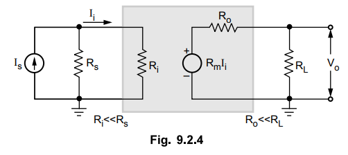
•
In this amplifier an output voltage is proportional to the input signal current
and the proportionality factor is independent on the source and load
resistances.
•
Ideally, this amplifier must have zero input resistance Ri and zero output
resistance Ro.
•
For practical transresistance amplifier we must have Ri << Rs
and Ro << RL. Since Ri << RL,
Since R1 << Rs, Ii
= Is and since Ro << RL, Vo = Rm Ij.
where
Rm = Vo / Is is the transfer or mutual
resistance Is

Review Questions
1. Draw the equivalent circuit of a voltage amplifier.
AU : ECE : Dec.-04, Marks 2
2. Draw the equivalent circuit of a current amplifier.
3. Draw the equivalent circuit of transconductance amplifier.
4. Draw the equivalent circuit of transresistance amplifier.
Electron Devices and Circuits: Unit V: (a) Feedback Amplifiers : Tag: : with Equivalent circuit - Classification of Amplifiers
Related Topics
Related Subjects

Electron Devices and Circuits
EC3301 3rd Semester EEE Dept | 2021 Regulation | 3rd Semester EEE Dept 2021 Regulation