Electron Devices and Circuits: Unit IV: Multistage and Differential Amplifiers
Classification of Power Amplifiers
• The position of the quiescent point on the load line decides the class of operation of the power amplifier. The various classes of the power amplifiers are : i) Class A ii) Class B iii) Class C iv) Class AB v) Class D.
Classification of Power Amplifiers
AU
: May-17, Dec.-17
•
The position of the quiescent point on the load line decides the class of
operation of the power amplifier. The various classes of the power amplifiers
are :
i)
Class A ii) Class B iii) Class C iv) Class AB v) Class D.
1. Class A Amplifiers
•
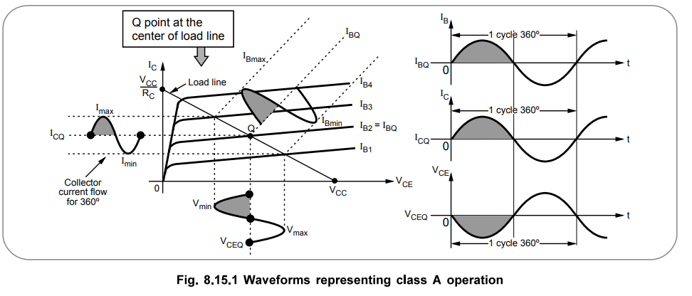
The power amplifier is said to be class A amplifier if the Q point and the
input signal are selected such that the output signal is obtained for a full
input cycle.
Important
Concept
For
this class, position of the Q point is approximately at the midpoint of the
load line.
•
For all values of input signal, the transistor remains in the active region and
never enters into cut-off or saturation region.
•
The collector current flows for 360° (full cycle) of the input signal. In other
words, the angle of the collector current flow is 360° i.e. one full cycle.
•
The current and voltage waveforms for a class A operation are shown with the
help of output characteristics and the load line, in the Fig. 8.15.1.
•
As shown in the Fig. 8.15.1, for full input cycle, a full output cycle is
obtained. Here signal is faithfully reproduced, at the output, without any
distortion. This is an important feature of a class A operation.
•
The efficiency of class A operation is very small, lies between 25 % to 50 %.
2. Class B Amplifiers
•
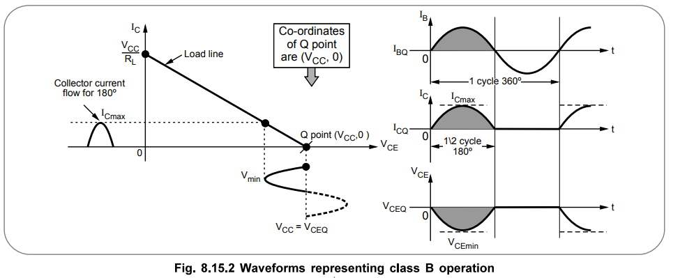
The power amplifier is said to be class B amplifier if the Q point and the
input signal are selected, such that the output signal is obtained only for one
half cycle for a full input cycle.
Important
Concept
For
this operation, the Q point is shifted on X-axis i.e. transistor is biased to
cut-off.
•
Due to the selection of Q point on the X-axis, the transistor remains, in the
active region, only for positive half cycle of the input signal. Hence this
half cycle is reproduced at the output.
•
But in a negative half cycle of the input signal, the transistor enters into a
cut-off region and no signal is produced at the output.
•
The collector current flows only for 180° (half cycle) of the input signal. In
other words, the angle of the collector current flow is 180° i.e. one half
cycle.
•
The current and voltage waveforms for a class B operation are shown in the Fig.
8.15.2.
•
As only a half cycle is obtained at the output, for full input cycle, the
output signal is distorted in this mode of operation.
•
To eliminate this distortion, practically two transistors are used in the
alternate half cycles of the input signal. Thus overall a full cycle of output
signal is obtained across the load. Each transistor conducts only for a half
cycle of the input signal.
•
The efficiency of class B operation is much higher than the class A operation,
upto 78.5 %.
3. Class C Amplifiers
•
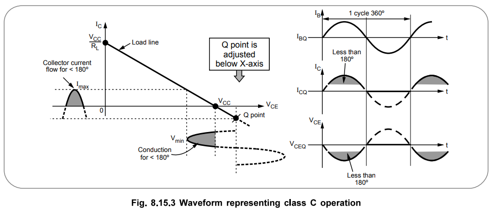
The power amplifiers is said to be class C amplifier, if the Q point and the
input signal are selected such that the output signal is obtained for less than
a half cycle, for a full input cycle.
Important
Concept
For
this operation, the Q point is to be shifted below X-axis.
•
Due to such a selection of the Q point, transistor remains active, for less
than a half cycle. Hence only that much part is reproduced at the output.
•
For remaining cycle of the input cycle, the transistor remains cut-off and no
signal is produced at the output.
•
The angle of the collector current flow is less than 180°.
•
The current and voltage waveforms for a class C amplifier operation are shown
in the Fig. 8.15.3.
Important
Concept
In
class C operation, the transistor is biased well beyond cut-off. As the
collector current flows for less than 180°, the output is much more distorted
and hence the class C mode is never used for A.F. power amplifiers.
•
But the efficiency of this class of operation is much higher and can reach very
close to 100 %.
•
The class C amplifiers are used in tuned circuits which are used in
communication areas and radio frequency circuits. These are also used in mixers
used in radio receivers and wireless communication circuits.
4. Class AB Amplifiers
•
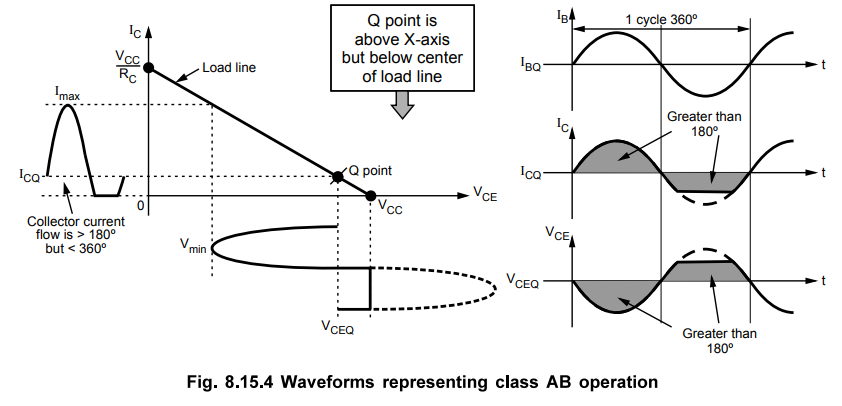
The power amplifier is said to be class AB amplifier, if the Q point and the
input signal are selected such that the output signal is obtained for more than
180° but less than 360°, for a full input cycle.
Important
Concept
The
Q point position is above X-axis but below the midpoint of a load line.
•
The current and voltage waveforms for a class AB operation, are shown in the
Fig. 8.15.4.
•
The transistor conducts for full positive half cycle and part of negative half
cycle.
•
The output is distorted but distortion can be eliminated.
•
The efficiency is more than class A but less than class B operation.
•
The class AB operation is important to eliminate cross-over distortion.
•
As it eliminates cross-over distortion, used in most of the audio systems,
radio receivers, T.V. receivers etc.
Review Questions
1. Give the
classification of large signal amplifiers.
2. Why class C
amplifiers are not used as the output stage in audio amplifiers ?
3. Describe the
working of class A and class C power amplifier in details with relevant
diagrams.
AU May-17, Marks 13
4. Explain the working
of class C power amplifier.
AU: Dec.-17, Marks 7
Electron Devices and Circuits: Unit IV: Multistage and Differential Amplifiers : Tag: : - Classification of Power Amplifiers
Electron Devices and Circuits: Unit IV: Multistage and Differential Amplifiers
Under Subject

Electron Devices and Circuits
EC3301 3rd Semester EEE Dept | 2021 Regulation | 3rd Semester EEE Dept 2021 Regulation
Related Subjects
Probability and complex function
MA3303 3rd Semester EEE Dept | 2021 Regulation | 3rd Semester EEE Dept 2021 Regulation

Electromagnetic Theory
EE3301 3rd Semester EEE Dept | 2021 Regulation | 3rd Semester EEE Dept 2021 Regulation

Digital Logic Circuits
EE3302 3rd Semester EEE Dept | 2021 Regulation | 3rd Semester EEE Dept 2021 Regulation
Electron Devices and Circuits
EC3301 3rd Semester EEE Dept | 2021 Regulation | 3rd Semester EEE Dept 2021 Regulation

Electrical Machines I
EE3303 EM 1 3rd Semester EEE Dept | 2021 Regulation | 3rd Semester EEE Dept 2021 Regulation
C Programming and Data Structures
CS3353 3rd Semester EEE, ECE Dept | 2021 Regulation | 3rd Semester EEE Dept 2021 Regulation