Electrical Machines: Unit II: D.C. Generators
Compound Generator
with Example Problems | DC Generators
Depending upon the connection of shunt and series fileld winding, compound generator is further classified as : i ) Long shunt compound generator.
Compound
Generator
AU: May-04,05,13,15,
Dec.-06,07,10,11,19
•
In this type, the part of the field winding is connected in parallel with
armature and part in series with the armature. Both series and shunt field
windings are mounted on the same poles. Depending upon the connection of shunt
and series fileld winding, compound
generator is further classified as : i ) Long shunt compound generator.
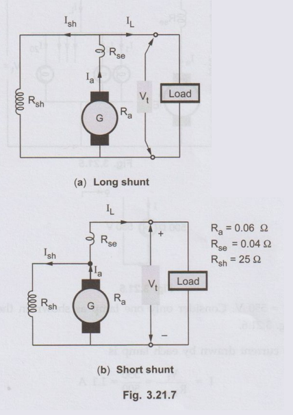
1. Long Shunt Compound
Generator
•
In this type, shunt field winding is connected across the series combination of
armature and series field winding as shown in the Fig. 3.21.1.
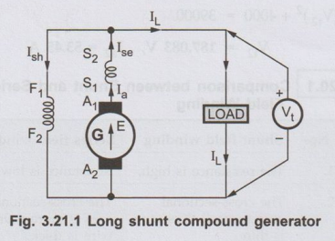
Voltage
and current relations are as follows.
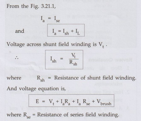
From
the Fig. 3.21.1,
2. Short Shunt
Compound Generator
•
In this type, shunt field winding is connected, only across the armature,
excluding series field winding as shown in the Fig. 3.21.2.
Voltage
and current relations are as follows.
For
the Fig. 3.21.2., Ia = Ise + Ish
And Ise = IL
•
ஃ
Ia = IL + Ish
•
The drop across shunt field winding is drop across the armature only and not
the total Vt in this case. So drop across shunt field winding is E -
Ia Ra
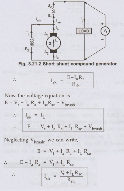
•
Any of the two above expressions of Ish can be used, depending on
the quantities known while solving the problems.
3. Cumulative and
Differential Compound Generator
•
It is mentioned earlier that the two windings, shunt and series field are wound
on the same poles. Depending on the direction of winding on the pole, two
fluxes produced by shunt and series field may help or may oppose each other.
This fact decides whether generator is cumulative or differential compound. If
the two fluxes help each other as shown in Fig. 3.21.3 the generator is called cumulative
compound generator.
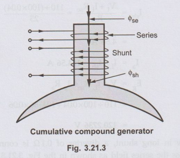
where
ϕT
= ϕsh + ϕse
Where
Фsh = Flux produced by shunt.
ϕse
= Flux produced by series, field windings.
•
If the two windings are wound in such a direction that the fluxes produced by them
oppose each other then the generator is called differential compound generator.
This is shown in the Fig. 3.21.4.
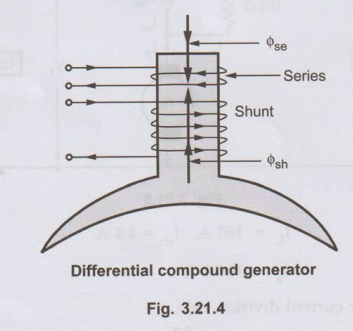
ϕΤ
= ϕsh = ϕse
Where
ϕsh = Flux produced by shunt field winding.
ϕse
= Flux produced by series field winding.
Ex. 3.21.1
A long shunt d.c. compound generator
drives 20 lamps, all are connected in parallel. Terminal voltage is 550 Ω with
each lamp resistance as 500Ω. If Rsh = 25Ω Ra = 0.06 Ω
and Rse = 0.04 Ω, calculate the current and the generated e.m.f.
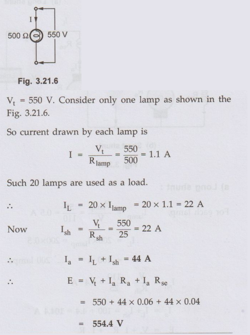
Sol.
Consider the arrangement as shown in the Fig. 3.21.5.
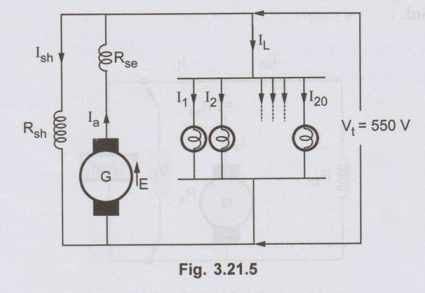
As
all lamps are in parallel, the voltage across all of them is same which is
terminal voltage of generator
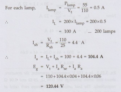
Ex. 3.21.2 In a 110 V compound generator, the armature, shunt and series windings are 0.06 Ω, 25 Ω and 0.04 Ω respectively. The load consists of 200 lamps each rated at 55 W, 110 V. Find the total e.m.f. and armature current, when the machine is connected for a) Long shunt b) Short shunt. How will the ampere-turns of the series windings be changed, if in (1), a diverter of resistance 0.1 Ω is connected across the series field. Ignore the armature reaction and brush drop. AU: Dec.-07, Dec.-10, Marks 8
Sol. :
(a) Long shunt
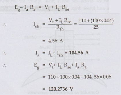
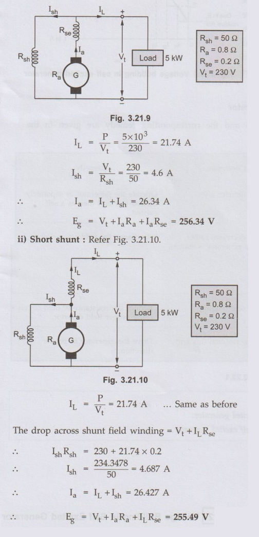
b) Short shunt :
The
load current remains same as IL = 100 A
The
drop across shunt field,
Now
in long shunt, a diverter of 0.1 Ω is connected across the series field as
shown in the Fig. 3.21.8.
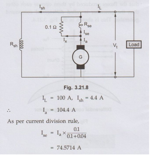
But
the turns of series field winding remains same. Hence originally ampere-turns
where [104.4 × N] and due to divert ampere-turns are [74.5714 × N] where N are
the number of turns of series field winding. Hence there is reduction of
[29.828 N] ampere-turns.
%
reduction in series field AT 29.828 × 100 / 104.4 × N
=
28.57%
Ex. 3.21.3
A compound generator has armature, series
and shunt field resistances of 0.8 ohm, 0.2 ohm and 50 ohm respectively and
supplies 5 kW at 230 V. Calculate the EMF generated in the armature, when it is
connected as i) Long shunt and ii) Short shunt.
AU May-15, Dec. 19, Marks 8
Sol.: i) Long shunt :
Refer Fig. 3.21.9.
Review Questions
1. With schematic
diagrams, explain the working principle of different types of dc generator
based on its excitation. AU May-13, Marks 16
2.What is meant by
circuit model of d.c. generator? Explain all of them in detail. AU: May-05, Marks 10
3. A 20 kW short shunt compound generator works on full load with terminal voltage of 250 V. Assume Ra= 0.05 Ω, Rse = 0.025 Ω and Rsh100 Ω, calculate the generated e.m.f.
(Ans.: 256.126 V)
4. A long shunt compound generator delivers 50 A load at 500 V. Find induced e.m.f. and the armature current. Assume Ra= 0.05Ω, Rse =0.03Ω and Rsh = 250Ω and brush drop of 1 VI brush. If flux per pole is 25 mWb with 250 number of armature conductors. Calculate speed of the prime mover. The machine has 6 poles with wave type armature winding. If same generator is connected as short shunt type, to supply same load at same voltage, at what speed it should be driven?
(Ans.: 506.16 V, 52 A, 1619.71 r.p.m., 1619.52 r.p.m.)
5. A four pole, lap wound long shunt compound generator has 1200 armature conductors. The armature, series field and shunt field resistances are 0.1 Ω, 0.15 Ω and 250 Ω, respectively. If flux per pole is 0.075 Wb. Calculate the speed at which the machine should be driven so that it can deliver the load of 50 kW at 500 V. Take overall voltage drop due to brush contact as 2 volts.
[Ans. 351.67 r.p.m.]
6. A long-shunt compound generator delivers a load current of 50 A at 50 V and has armature, series field and shunt field resistances of 0.05 Ω, 0.03Ω, and 250 Ω respectively. Calculate the generated voltage and the armature current. Allow 1 V per brush for contact drop. AU: Dec.-06
[Ans.: 52 A, 506.16 V]
Electrical Machines: Unit II: D.C. Generators : Tag: : with Example Problems | DC Generators - Compound Generator
Related Topics
Related Subjects

Electrical Machines I
EE3303 EM 1 3rd Semester EEE Dept | 2021 Regulation | 3rd Semester EEE Dept 2021 Regulation