Electrical Machines: Unit II: D.C. Generators
Concept of Armature Reaction
D.C. Generators
To understand the concept of armature reaction, consider a two pole d.c. generator. For simplicity we will assume that the brushes are touching the armature conductors directly, although, they touch commutator segments in actual practice.
Concept
of Armature Reaction
AU: Dec.-05, 09, 15, May-10, 16
•
To understand the concept of armature reaction, consider a two pole d.c.
generator. For simplicity we will assume that the brushes are touching the
armature conductors directly, although, they touch commutator segments in
actual practice.
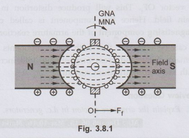
•Assuming
that the generator is not driving any load. So that there is no current in the
armature conductors. The distribution of main field flux under this case is as
shown in the Fig. 3.8.1. The flux is distributed symmetrically with respect to
axis called polar axis which is line joining the centres of N and S poles. The
direction of flux produced by field coil is from left to right through an
armature core and lines of force through the core are parallel to field axis.
•
The axis along which there is noe.m.f. induced in the armature conductors is
called. Magnetic Neutral Axis (MNA).
From the Fig. 3.8.1 it can be seen that magnetic neutral axis (MNA) and
Geometric Neutral Axis (GNA) coincides with each other. The geometric neutral
axis is nothing but the axis of symmetry between the poles.
•
The brushes are always kept along MNA.
Key Point:
Thus MNA can also be called 'axis of commutation' since reversal of current
takes place along this axis.
•
As shown in the Fig. 3.8.1, vector OFf, represents the m.m.f.
producing the main flux both in magnitude as well as in the direction. MNA is
perpendicular to vector OFf
•
Now we will consider that the field coils are unexcited whereas the armature
conductors are
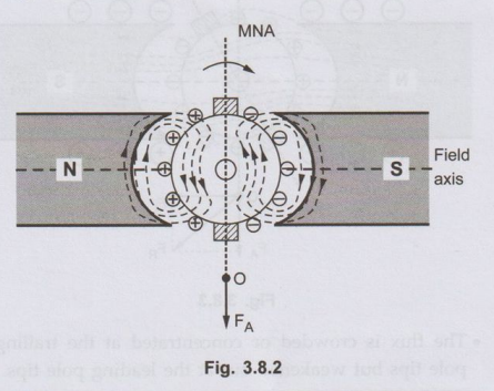
•Now
we will consider that the field coils are unexcited whereas the armature
conductors are carrying current. Under this case the field set up by the
armature conductors is as ahown in the Fig.3.8.2.
•
The direction of current in armature conductors can be found by applying
Fleming's right hand rule. The current will flow in the same direction if the
generator is driving load. Under N pole, the current is flowing in downward
direction whereas under S pole, the current is flowing in upward direction.
•
The direction of the flux produced by current carrying conductors is vertically
downwards in the armature core. This flux is symmetrical about a brush axis. In
other words current carrying armature conductors try to magnetise the armature
core along the brush axis.
•
The vector OFA the shown in the Fig. 3.8.2 represents armature
m.m.f. both in magnitude and direction. This m.m.f. depends on the magnitude of
the armature current.
•
Uptil now we have considered the main m.m.f. and armature m.m.f. separately as
if they are existing independently.
Key Point:
In practice the two m.m.f.s exist simultaneously in the generator under load conditions.
•
Now the flux through the armature is not uniform and symmetrical. The flux gets
distorted. Due to interaction of two fluxes, the resultant flux distribution is
changed as shown in the Fig. 3.8.3.
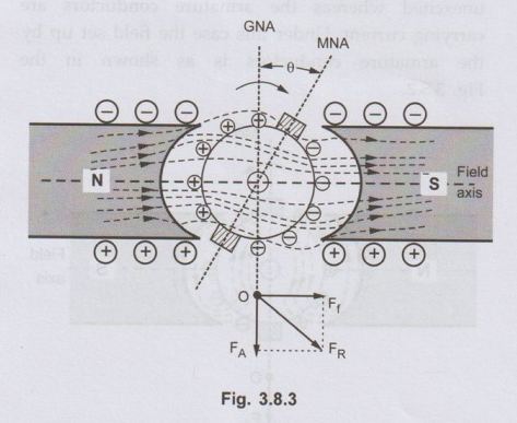
•
The flux is crowded or concentrated at the trailing pole tips but weakened out
at the leading pole tips.
Key Point:
The pole tip which is met first during rotation by armature conductors is known
leading pole tip and other is known as trailing pole tip.
•
The resultant m.m.f. OFR can be found by vectorially combining OFf,
and OFA
• The new position of MNA is also shown which
is perpendicular to the resultant m.m.f. vector OFR The MNA gets
shifted through an angle θ so that brushes are also shifted and are along new
MNA.
•
Due to this brush shift, the armature conductors as well as armature current is
redistributed. Some of D.C. Generators the armature conductors which were
earlier under the influence of S pole now come under N pole and vice versa.
•
This regrouping of armature conductors
and armature current is as shown in the Fig. 3.8.4. It can also be seen that
the brush shifts in the same direction as that of direction of rotation of
armature.
•
The conductors on the left of new position of MNA carry current downwards and
those to the right carry current upwards. The armature m.m.f. is now along new
position of MNA represented by vector OFR in the Fig. 3.8.4. It is inclined at
an angle 0 to the left instead of being vertical.
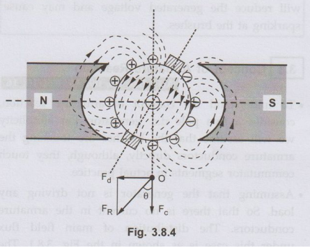
•The
armature m.m.f. represented by vector OFR can be resolved into two components,
OFd parallel to the polar axis and OF, perpendicular to the axis. The component
OF is in direct opposition with field m.m.f. vector OF. This will tend to
reduce the total flux. Hence this component is called demagnetising component
of the armature reaction whereas the other component OF is at right angles to
vector OF. This will produce distortion in the main field. Hence this component
is called cross magnetising component of the armature reaction.
•
It can be observed that both the components viz. demagnetising and cross
magnetizing, will increase with increase in armature current.
Review Question
1. Explain the
armature reaction in d.c. generators. AU : Dec.-05,06,15, May-10,16, Marks 16
Electrical Machines: Unit II: D.C. Generators : Tag: : D.C. Generators - Concept of Armature Reaction
Related Topics
Related Subjects

Electrical Machines I
EE3303 EM 1 3rd Semester EEE Dept | 2021 Regulation | 3rd Semester EEE Dept 2021 Regulation