Linear Integrated Circuits: Unit II: Characteristics of Op-amp
Concept of Frequency Compensation used in operational amplifiers
Op-amp
Consider the system with three break or corner frequencies. This is possible in practice due to the capacitive component produced by the various number of stages.
Concept of Frequency Compensation
May-03,
04, 09, 16, Dec.-06
It
is seen earlier that the op-amp circuit with single break or comer frequency is
inherently stable.
Consider
the system with three break or corner frequencies. This is possible in practice
due to the capacitive component produced by the various number of stages.
The
open loop frequency dependent transfer function of such a system can be assumed
as,
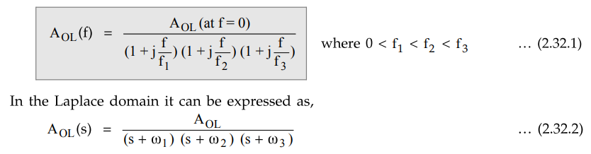
where AOL = gain at 0 frequency or d.c. gain and w1, 2, 3 are the corner frequency values such that 0 < ω1 < ω2 < ω3·
The
phase shift introduced by such loop gain is,
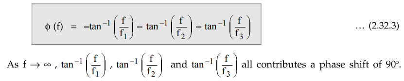
Hence
at high frequencies ϕ (f) → - 270°.
Thus
the phase shifts of each stage θ1, θ2 and θ3
add together to give the total phase shift of op-amp where,

At
f = f1, θ1 = 45° while θ2 and θ3
are negligible. At f = f2, 01 is almost - 90° as θ1 f2
> f1 and θ2 = -45°. Thus the total phase shift becomes
- 135°. The θ3 is still small. At θ1 90° as f3f2>
f1 while 03 reaches to - 45°. Thus the total phase shift becomes 90°
- 90° - 45° = - 225°.
This
is the additional phase shift to – 180° phase shift which is present between
inverting terminal and output terminal.
Due
to such additional phase shift op-amp may behave oscillatory and circuit
becomes unstable. This is shown in the Fig. 2.32.1.
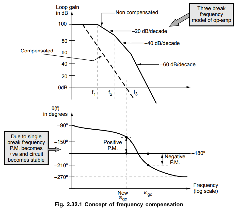
Thus
as seen from the frequency response of noncompensated op-amp, due to additional
phase shift, at ω = ωgc, there is chance that total phase shift
becomes almost - 360° and circuit becomes unstable. The phase margin is
negative in such a case.
To build the oscillations the total phase shift need not be exactly - 360° but if it is more than - 315° and AOL β > 1 then oscillations may start.
To avoid the oscillations, the total phase shift should not be greater than - 315° i.e. due to the op-amp, excluding -180° between inverting terminal and output, the phase shift should not be greater than - 315° + 180° = -135°
Minimum
phase margin = 180° - 135° = + 45°
Thus
for op-amp circuit stability, it is necessary to have phase margin of + 45°.
This
is possible by providing necessary compensation so that only one breakover
frequency exists.
Due
to this, phase shift of op-amp cannot increase beyond - 90°. Thus there is no
chance that Op-amp phase shift becomes -135° and phase margin is automatically
more than + 45°.
This
technique of compensation is called frequency compensation technique. Using
this technique, the op-amp is converted to single break frequency op-amp. The
frequency response of such op-amp has only one roll off rate of -20 dB/dec and
is as shown dotted in the Fig. 2.32.1.
Key
Point The method of modifying loop gain frequency
response of the op-amp so that it behaves like single break frequency response
which provides sufficient positive phase margin is called frequency
compensation technique.
Op-amp
circuits with high closed loop gain are early to compensate while op-amp
circuits with low closed loop gain are difficult from compensation point of
view to provide stability.
When
a lower closed loop gain and large bandwidth is required for a system, suitable
compensation technique is used.
The
two types of compensation techniques are used in practice namely, i) External
compensation ii) Internal compensation.
Review Question
1. Explain on frequency compensation used in operational
amplifiers.
May-03, 04, 16, Marks 12, Dec.-06, Marks 10, May-09, Marks 8
Linear Integrated Circuits: Unit II: Characteristics of Op-amp : Tag: : Op-amp - Concept of Frequency Compensation used in operational amplifiers
Related Topics
Related Subjects

Linear Integrated Circuits
EE3402 Lic Operational Amplifiers 4th Semester EEE Dept | 2021 Regulation | 4th Semester EEE Dept 2021 Regulation