Electrical Machines: Unit IV: Single Phase Transformer
Conditions for Satisfactory Parallel for Operation
Single Phase Transformer
•The conditions that must be followed for satisfactory parallel operation of transformers are as follows:
Conditions
for Satisfactory Parallel for Operation
AU: Dec.-02, 03, 05, 08, 19,
May-07, 15
•The
conditions that must be followed for satisfactory parallel operation of
transformers are as follows:
1)
The supply system voltage and frequency must suit the primary windings of the
transformers.
2)
The transformers that are connected must have same polarity. In case of three
phase transformers the transformers should have same angular displacement and
same phase sequence.
3)
The voltage ratios of primaries and secondaries of the transformers must be
same.
4)
The percentage impedances should be equal in magnitude and have same X/R ratio
in order to avoid circulating currents and operating at different power
factors.
5)
If the transformers have the different KVA ratings, the equivalent impedances
should be inversely proportional to individual kVA rating to avoid circulating
currents.
1. Explanation of Conditions
The
condition (1) can be easily satisfied.
•
The condition (2) is an important condition for the faithful parallel operation
of transformers. The secondary windings of the two transformers which are
connected in parallel are either in phase with each other having zero degree
phase displacement between the voltages or the voltages are in opposite
time-phase relationship with a phase difference of 180° between them. A closed
series circuit is formed by this parallel connection.
•
If two voltages are having same phase relationship, the induced voltages from
either common connection to the other are in the same direction. Thus there is
no current flow in the series circuit. Thus the parallel operation works satisfactorily
with no load connected. The windings so connected will have same polarity.
•
If the two voltages are in phase opposition, the induced voltages from either
common connection to the other are in opposite directions, hence adding to one
another in the series circuit. Thus a large current will flow in the series
circuit which is equivalent to a short circuit on both transformers. The two
windings will have opposite polarity and parallel operation will not work
properly.
•
This polarity designation should not be confused with the terms additive
polarity and subtractive polarity as applied to individual units which are used
only to give the relative directions of induced voltages and are helpful in
proper paralleling of the transformers.
•
If the lead marking is not available while making parallel connection then it
is suggested that the two leads located in similar positions with respect to
the bank is connected together and a fuse of low current rating is inserted
between remaining leads. With windings having similar polarity the voltage
across the fuse will be zero and no current will flow. If the windings are of
opposite polarity the voltage across the fuse will be twice the voltage of
either winding. Thus short circuit current will flow and fuse will blow out.
Thus in this case the connections are to be interchanged for reliable parallel
operation.
•
For parallel operation of three phase transformers having same voltage ratio,
polarity may not be required to be considered. For satisfactory operation, the
angular displacement and phase rotation between the two units to be paralleled
must be the same. Paralleling of three phase transformers is simplified by
standardizing the lead markings and various three phase connections have been
placed in three different groups depending upon their angular displacement. The
advantage of this is that it is not required to test for polarity, angular
displacement and phase rotation.
•
If condition (3) i.e. voltage ratios of primaries and secondaries of the
transformers must be same is not satisfied the difference in voltage between
the windings will cause a current to flow in the circuit at all time. This
circulating current will be limited only by the sum of the impedances of the
two transformers. Though this condition is not perfectly met still parallel
operation is possible at the cost of the circulating current. When load is
connected across the secondaries this circulating current in local circuit will
produce unequal loading condition.
•
The amount of circulating current can be calcul by making use of following
formula,
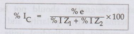
where
% IC = Percentage circulating current in % of normal load current of
one
transformer.
%
e = Percentage of normal voltage indicating difference in voltage between the
two windings.
%
I Z1 = Percentage impedance of transform 1.
%
I Z2 = Percentage impedance of transform 2.
•
In the above formula it is assumed that the capa of both the units as the same.
Key Point:
With different capacities, the perc impedances in the formula should be based
up the same kVA rating and the percent circulati current is then percent of
normal load current this same kVA rating.
•
If there is small difference between the ratios transformers connected in
parallel then it produce relatively large circulating current.
Key Point: For satisfactory parallel operation,
circulating current should not exceed 10 percent normal load current.
•
By making use of balance coil in case of sin phase and three phase transformers
with differ voltage ratios parallel operation will be reliable.
•
With violence of condition (4) i.e. if the percent impedances are not equal in
magnitude then a parallel operation is possible. Under this case impedance
triangles are not identical in shape a size. Also the two transformers will operate
different power factors from the power factor of combined load. One transformer
will operate higher power factor and the other will operate a lower power
factor that of combined load. effect of this will be that the two transformers
will not share the load in proportion to their kVA ratings.
•
The ratio of resistance to reactance must also be same for each of the
transformers. So that the currents in each of the transformers are in phase. I
these ratios are not same, the currents in the transformers are not in phase
and the sum of the winding current will be greater than the line current.
•If
the percentage impedance of all the unit connected in parallel is same then the
load wil divide in the individual units in the ratio of thei capacities even if
the error is introduced due to unequal ratio of resistance and reactance. The
tota permissible load will be equal to the sum Of capacities of the individual
units connected ir parallel.
Review Questions
1. Explain in detail
about the parallel operation of single phase transformers. AU: Dec.-03, 05, 08,
19, Marks 16
2. Explain the need
for parallel operation of single-phase transformers. Give the conditions to be
satisfied for their successful operation. AU: May-07, 15, Dec.-02, 05, Marks 6
Electrical Machines: Unit IV: Single Phase Transformer : Tag: : Single Phase Transformer - Conditions for Satisfactory Parallel for Operation
Related Topics
Related Subjects

Electrical Machines I
EE3303 EM 1 3rd Semester EEE Dept | 2021 Regulation | 3rd Semester EEE Dept 2021 Regulation