Electrical Machines II: UNIT V: a. Single Phase Induction Motors
Conducting Tests on Single Phase Induction Motor
The tests usually conducted are : 1. No load test or open circuit test 2. Blocked rotor test or short circuit test
Conducting Tests on Single Phase Induction Motor AU
: May-10, Dec.-14, 17
Similar
to a three phase induction motor, the various tests can be performed on single
phase induction motor. The results of these tests can be used to obtain the
equivalent circuit parameters of a single phase induction motor. The tests
usually conducted are :
1.
No load test or open circuit test
2.
Blocked rotor test or short circuit test
1. No Load Test
The
test is conducted by rotating the motor without load. The input current,
voltage and power are measured by connecting the ammeter, voltmeter and
wattmeter in the circuit. These readings are denoted as V0, I0
and W0.
Now
W0 = V0 I0 cos ϕ
cos
ϕ0 = W0 / V0 I0 = No load power
factor
The
motor speed on no load is almost equal to its synchronous speed hence for practical
purposes, the slip can be assumed zero. Hence r2 / s becomes and
acts as open circuit in the equivalent circuit. Hence for forward rotor
circuit, the branch r2/s + j x2 gets eliminated.
While
for a backward rotor circuit, the term r2/(2 - s) tends to r2/2.
Thus X0 is much higher than
the impedance r2 / 2 + j x2. Hence it can be assumed that
no current can flow through xm and that branch can be eliminated.
So
circuit reduces to as shown in the Fig.8.10.1
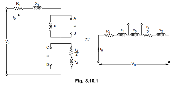
Now
the voltage across x0 is VVB
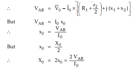
Thus
magnetising reactance X0 can be determined.
The
no load power W0 is nothing but the rotational losses.
2. Blocked Rotor Test
In
blocked rotor test, the rotor is held fixed so that it will not rotate. A
reduced voltage is applied to limit the short circuit current. This voltage is
adjusted with the help of autotransformer so that the rated current flows
through main winding. The input voltage, current and power are measured by
connecting voltmeter, ammeter and wattmeter respectively. These readings are
denoted as VSC, ISC and WSC.
Now
as rotor is blocked, the slip s = 1. Hence the magnetising reactance xo is much
higher than the rotor impedance and hence it can be neglected as connected in
parallel with the rotor. Thus the equivalent circuit for blocked rotor test is
as shown in the Fig. 8.10.2.
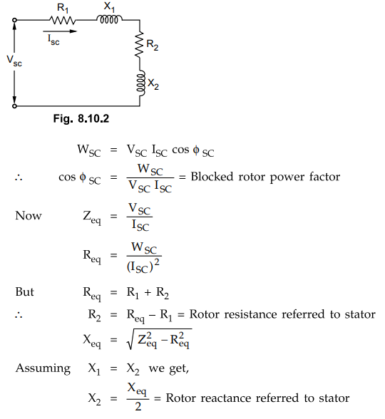
The
stator resistance R1 is measured by voltmeter-ammeter method, by
disconnecting the auxiliary winding and capacitors present if any. Due to skin
effect, the a.c. resistance is 1.2 to 1.5 times more than the d.c. resistance.
Thus
with these two tests, all the parameters of single phase induction motor can be
obtained.
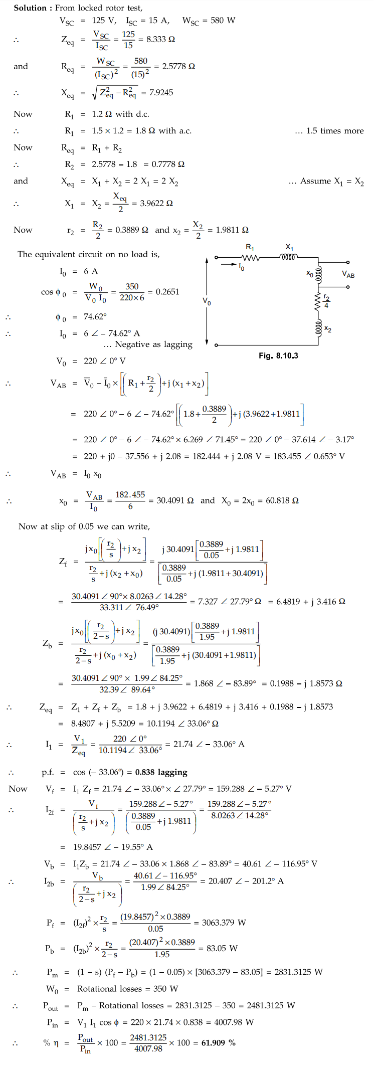
Example
8.10.1 A 220 V, 1 phase, induction motor has following
test results :
N.
L. Test: V = 220 V, I = 6 A, P = 350 W
Locked
rotor Test : V = 125 V, I = 15 A, P = 580 W
Stator
resistance : 1.2 Ω with direct current
Estimate
the p.f. and efficiency when the slip is 0.05.
Solution
:
Examples
for Practice
Example
8.10.2 The following data shown result on a 230 V, 50
Hz capacitor start single-phase induction motor at standstill :
Main
winding : 100 V, 2 A, 40 W
Auxiliary
winding, 80 V, 2.0 A, 50 W
Determine
the value of capacitance for obtaining the maximum starting torque.
[Ans.:
C = 67.52 µF]
Example
8.10.3 The following test results were obtained in case
of a 220 V single phase induction motor :
Free
running test: 220 V, 5.8 A, 310 W
Blocked
rotor test : 120 V, 13.8 A, 530 W
Stator
winding resistance = 1.4 Ω
Determine
the approximate equivalent circuit of a motor.
[Ans.:
X1 = X2 = 4.1191Ω R2 = 1.383 Ω Xa =
31.433, Xm = 62.867 Ω]
Example
8.10.4 A 220-V, 1-phase induction motor gave the
following test results :
Blocked-rotor
test : 120 V, 9.6 A, 460 W
No-load
test : 220 V, 4.6 A, 125 W
The
stator winding resistance is 1.5 Ω and during the blocked rotor test, the
starting winding is open. Determine the equivalent circuit parameters and core,
friction and windage losses.
[Ans.:
Z =12.5 Ω, Req =4.99 Ω,
X
= 11.46 5 Ω, R.2 = 3.49 Ω,
X1=
X2 = 5.78 Ω Zo = 47.826 Ω,
Xo=47A87
Ω, 74.798 W]
Review Questions
1. Explain the no-load test and blocked rotor test for obtaining
the equivalent circuit parameters of a single phase induction motor.
2. Draw the equivalent circuit of single-phase induction motor
and discuss the experimental procedure to obtain its parameters.
Electrical Machines II: UNIT V: a. Single Phase Induction Motors : Tag: Engineering Electrical Machines - II : - Conducting Tests on Single Phase Induction Motor
Related Topics
Related Subjects

Electrical Machines II
EE3405 Machine 2 EM 2 4th Semester EEE Dept | 2021 Regulation | 4th Semester EEE Dept 2021 Regulation