Electrical Machines II: UNIT III: a. Three Phase Induction Motor
Construction of Three Phase Induction Motor
Stator, Rotor
Basically, the induction motor consists of two main parts, namely 1. The part i.e. three phase windings, which is stationary called stator. 2. The part which rotates and is connected to the mechanical load through shaft called rotor.
Construction
Basically,
the induction motor consists of two main parts, namely
1.
The part i.e. three phase windings, which is stationary called stator.
2.
The part which rotates and is connected to the mechanical load through shaft
called rotor.
The
conversion of electrical power to mechanical power takes place in a rotor.
Hence rotor develops a driving torque and rotates.
1. Stator
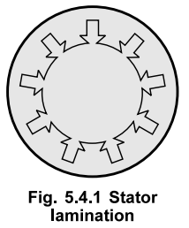
The
stator has a laminated type of construction made up of stampings which are 0.4
to 0.5 mm thick. The stampings are slotted on its periphery to carry the stator
winding. The stampings are insulated from each other. Such a construction
essentially keeps the iron losses to a minimum value. The number of stampings
are stamped together to build the stator core. The built up core is then fitted
in a casted or fabricated steel frame. The choice of material for the stampings
is generally silicon steel, which minimizes the hysteresis loss. The slots on
the periphery of the stator core carries a three phase winding, connected
either in star or delta. This three phase winding is called stator winding. It
is wound for definite number of poles. This winding when excited by a three
phase supply produces a rotating magnetic field as discussed earlier. The
choice of number of poles depends on the speed of the rotating magnetic field
required. The radial ducts are provided for the cooling purpose. In some cases,
all the six terminals of three phase stator winding are brought out which gives
flexibility to the user to connect them either in star or delta.
The
Fig. 5.4.1 shows a stator lamination.
2. Rotor
The
rotor is placed inside the stator. The rotor core is also laminated in
construction and uses cast iron. It is cylindrical, with slots on its
periphery. The rotor conductors or winding is placed in the rotor slots. The
two types of rotor constructions which are used for induction motors are,
1.
Squirrel cage rotor and 2. Slip ring or wound rotor
1.
Squirrel Cage Rotor
The
rotor core is cylindrical and slotted on its periphery. The rotor consists of
uninsulated copper or aluminium bars called rotor conductors. The bars are
placed in the slots. These bars are permanently shorted at each end with the
help of conducting copper ring called end ring. The bars are usually brazed to
the end rings to provide good mechanical strength. The entire structure looks
like a cage, forming a closed electrical circuit. So the rotor is called
squirrel cage rotor. The construction is shown in the Fig. 5.4.2.

As
the bars are permanently shorted to each other through end ring, the entire
rotor resistance is very very small. Hence this rotor is also called short
circuited rotor. As rotor itself is short circuited, no external resistance can
have any effect on the rotor resistance. Hence no external resistance can be
introduced in the rotor circuit. So slip ring and brush assembly is not
required for this rotor. Hence the construction of this rotor is very simple.
Fan
blades are generally provided at the ends of the rotor core. This circulates
the air through the machine while operation, providing the necessary cooling.
The air gap between stator and rotor is kept uniform and as small as possible.
In
this type of rotor, the slots are not arranged parallel to the shaft axis but
are skewed as shown in the Fig. 5.4.3.

The
advantages of skewing are,
1.
A magnetic hum i.e. noise gets reduced due to skewing hence skewing makes the
motor operation quieter.
2.
It makes the motor operation smooth.
3.
The stator and rotor teeth may get magnetically locked. Such a tendency of magnetic
locking gets reduced due to skewing.
4.
It increases the effective transformation ratio between stator and rotor.
2.
Slip Ring Rotor or Wound Rotor
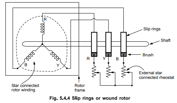
In
this type of construction, rotor winding is exactly similar to the stator. The
rotor carries a three phase star or delta connected, distributed winding, wound
for same number of poles as that of stator. The rotor construction is laminated
and slotted. The slots contain the rotor winding. The three ends of three phase
winding, available after connecting the winding in star or delta, are
permanently connected to the slip rings. The slip rings are mounted on the same
shaft. We have seen that slip rings are used to connect external stationary
circuit to the internal rotating circuit. So in this type of rotor, the
external resistances can be added with the help of brushes and slip ring
arrangement, in series with each phase of the rotor winding. This arrangement
is shown in the Fig. 5.4.4.
Key Point This way the
value of rotor resistance per phase can be controlled. This helps us to control
some of the important characteristics of the motor like starting torque, speed
etc.
In
the running condition, the slip rings are shorted. This is possible by
connecting a metal collar which gets pushed and connects all the slip rings
together, shorting them. At the same time brushes are also lifted from the slip
rings. This avoids wear and tear of the brushes due to friction. The
possibility of addition of an external resistance in series with the rotor,
with the help of slip rings is the main feature of this type of rotor.
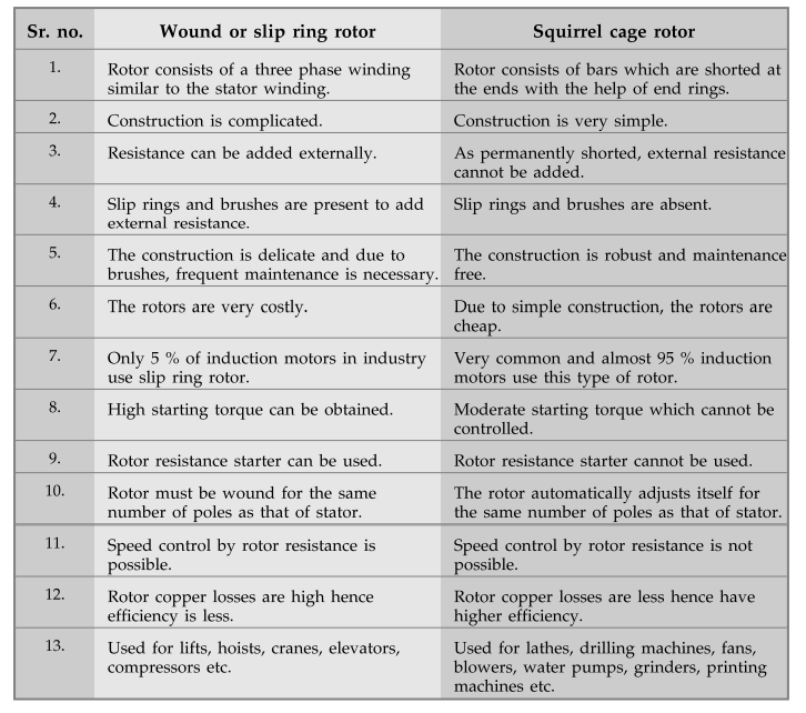
3.
Comparison of Squirrel Cage and Wound Rotor
Wound
or slip ring rotor
1.
Rotor consists of a three phase winding similar to the stator winding.
2.
Construction is complicated.
3.
Resistance can be added externally.
4.
Slip rings and brushes are present to add external resistance.
5.
The construction is delicate and due to brushes, frequent maintenance is
necessary.
6.
The rotors are very costly.
7.
Only 5 % of induction motors in industry use slip ring rotor.
8.
High starting torque can be obtained.
9.
Rotor resistance starter can be used.
10.
Rotor must be wound for the same number of poles as that of stator.
11.
Speed control by rotor resistance is possible.
12. Rotor copper losses are high hence
efficiency is less.
13.
Used for lifts, hoists, cranes, elevators, compressors etc.
Squirrel
cage rotor
1.
Rotor consists of bars which are shorted at the ends with the help of end
rings.
2.
Construction is very simple.
3.
As permanently shorted, external resistance cannot be added.
4.
Slip rings and brushes are absent.
5.
The construction is robust and maintenance free.
6.
Due to simple construction, the rotors are cheap.
7.
Very common and almost 95 % induction motors use this type of rotor.
8.
Moderate starting torque which cannot be controlled.
9.
Rotor resistance starter cannot be used.
10.
The rotor automatically adjusts itself for the same number of poles as that of
stator.
11.
Speed control by rotor resistance is not possible.
12.
Rotor copper losses are less hence have higher efficiency.
13.
Used for lathes, drilling machines, fans, blowers, water pumps, grinders,
printing machines etc.
Review Questions
1. Describe the constructional features of squirrel cage and
slip ring induction motors. Discuss the merits of one over other.
2. Compare squirrel cage and wound rotor constructions of
induction motor.
Electrical Machines II: UNIT III: a. Three Phase Induction Motor : Tag: Engineering Electrical Machines - II : Stator, Rotor - Construction of Three Phase Induction Motor
Related Topics
Related Subjects

Electrical Machines II
EE3405 Machine 2 EM 2 4th Semester EEE Dept | 2021 Regulation | 4th Semester EEE Dept 2021 Regulation