Microprocessors and Microcontrollers: Unit IV: (a) Programmable Peripheral Interface (PPI) - 8255
Control Word Formats
Programmable Peripheral Interface (PPI) - 8255
he ports of the 8255 can then be programmed for any other mode by writing a single control word into the control register, when required.
Control Word Formats
AU
: May-04, 18, Dec.-05,07, 08, 16, 19
A
high on the RESET pin causes all 24 lines of the three 8-bit ports to be in the
input mode. All flip-flops are cleared and the interrupts are reset. This
condition is maintained even after the RESET goes low. The ports of the 8255
can then be programmed for any other mode by writing a single control word into
the control register, when required.
1. For Bit Set/Reset Mode
Fig.
8.5.1 shows bit set/reset control word format.

The
eight possible combinations of the states of bits D3 - D1
(B2 B1 B0 )in the Bit Set-Reset format (BSR)
determine particular bit in PC0 – PC7 being set or reset
as per the status of bit D0. A BSR word is to be written for each
bit that is to be set or reset. For example, if bit PC3 is to be set
and bit PC4 is to be reset, the appropriate BSR words that will have
to be loaded into the control register will be, 0×××0111 and 0×××100 0,
respectively, where × is don't care.
The
BSR word can also be used for enabling or disabling interrupt signals generated
by Port C when the 8255 is programmed for Mode 1 or 2 operation. This is done
by setting or resetting the associated bits of the interrupts. This is
described in detail in next section.
2. For I/O Mode
The
mode definition format for I/O mode is shown in Fig. 8.5.2. The control words
for both, mode definition and Bit Set-Reset are loaded into the same control
register, with bit D7 used for specifying whether the word loaded
into the control register is a mode definition word or Bit Set-Reset word. If D
is high, the word is taken as a mode definition word, and if it is low, it is
taken as a Bit Set-Reset word. The appropriate bits are set or reset depending
on the type of operation desired, and loaded into the control register.

Example
8.5.1 Write a program to initialize 8255 in
the configuration given below :
1.
Port A : Simple input
2.
Port B : Simple output
3.
Port CL : Output
4.
Port CU : Input
Assume
address of the control word register of 8255 as 83H.
Example
8.5.2 Write a program to initialize 8255 in the
configuration given below :
1.
Port A : Output with handshake
2.
Port B : Input with handshake
3.
Port CL : Output
4.
Port CU : Input
Assume
address of the control word register of 8255 as 23H.
Solution
:

Source
program :
MVI
A, AEH ; Load control word
OUT
23H ; Send control word
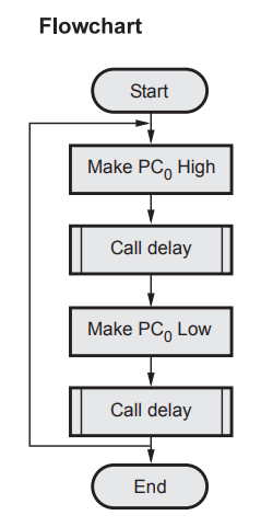
Lab Experiment 8.5.1 : Blink port C bit
o of 8255.
Statement :
Write a program to blink Port C bit 0 of the 8255. Assume address of control
word register of 8255 as 83H. Use Bit Set/Reset mode.
Solution
:
Control word to make bit 0 high.

Source program :
BACK
: MVI A, 01H ; Load bit pattern to make PC0 high
OUT
83H ; Send it to control word register
CALL
DELAY ; Call Delay subroutine
MVI
A, OOH ; Load bit pattern to make PC0 Low
OUT
83H ; Send it to control word register
CALL
Delay ; Call Delay subroutine
JMP
BACK ; Repeat
Review Questions
1. Show the control
word format of 8255 and explain how each bit is programmed.
AU : May-04, 18,
Dec.-19, Marks 4
2. Explain the bit
set/reset mode of 8255.
3. Write the format cf
control word for 8255 PPI.
Microprocessors and Microcontrollers: Unit IV: (a) Programmable Peripheral Interface (PPI) - 8255 : Tag: : Programmable Peripheral Interface (PPI) - 8255 - Control Word Formats