Electrical Machines II: UNIT IV: Starting and Speed Control of Three Phase Induction Motor
Controlling Number of Poles
Three Phase Induction Motor
In this method, it is possible to have one, two or four speeds in steps, by changing the number of stator poles.
Controlling Number of Poles
The
method is called Pole Changing method of controlling the speed. In this
method, it is possible to have one, two or four speeds in steps, by changing
the number of stator poles. A continuous smooth speed control is not possible
by this method.
The
stator poles can be changed by following methods :
1.
Consequent poles method
2.
Multiple stator winding method
3.
Pole amplitude modulation method.
1. Consequent Poles Method
In
this method, connections of the stator winding are changed with the help of
simple switching. Due to this, the number of stator poles get changed in the ratio
2:1. Hence either of the two synchronous speeds can be selected.
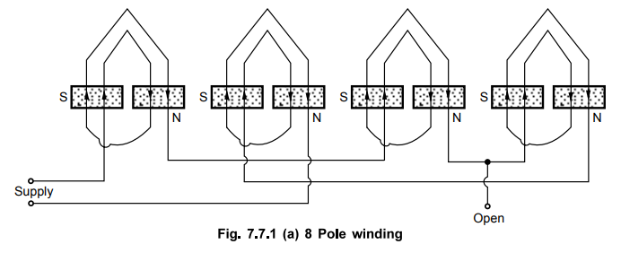
Consider
the pole formation due to single phase of a three phase winding, as shown in
the Fig. 7.7.1. There are three tapping points to the stator winding. The
supply is given to two of them and third is kept open.
It
can be seen that current in all the parts of stator coil is flowing in one
direction only. Due to this, 8 poles get formed as shown in the Fig. 7.7.1 (a).
So synchronous speed possible with this arrangement with 50 Hz frequency is Ns
= 750 r.p.m.
If
now the two terminals to which supply was given earlier are joined together and
supply is given between this common point and the open third terminal, the
poles are formed as shown in the Fig. 7.7.1 (b).
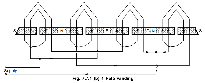
It
can be seen that the direction of current through two coils is different than
the direction of current through remaining two. Thus upward direction is
forming say S pole and downward say N. It can be observed that in this case
only 4 poles are formed. So the synchronous speed possible is 1500 r.p.m. for
50 Hz frequency.
Thus
series/parallel arrangements of coils can produce the poles in the ratio 2:1.
But the speed change is in step and smooth speed control is not possible.
Similarly the method can be used only for the squirrel cage type motors as
squirrel cage rotor adjusts itself to same number of poles as stator which is
not the case in slip ring induction motor. The method is used for the
applications such as elevators, traction motors and small motors used to drive
machine tools.
2. Multiple Stator Winding Method
In
this method instead of one winding, two separate stator windings are placed in
the stator core. The windings are placed in the stator slots only but are
electrically isolated from each other. Each winding is divided into coils to
which, pole changing with consequent poles, facility is provided.
Thus
giving supply to one of the two windings and using switching arrangement, two
speeds can be achieved. Same is true for other stator winding. So in all four
different speeds can be obtained.
The
various limitations of this method are,
1.
Can be applied to only squirrel cage motor.
2.
Smooth speed control is not possible. Only step changes in speed are possible.
3.
Two different stator windings are required to be wound which increases the cost
of the motor.
4.
Complicated from the design point of view.
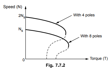
Typical
speed-torque characteristics of pole changing induction motor are shown in the
Fig. 7.7.2.
3. Pole Amplitude Modulation Method
The
basic disadvantage of other methods which is nonavailability of smooth speed
control, is eliminated by this method. The ratio of two speeds in this method,
need not be necessarily 2:1.
The
basic principle of this method is the modulation of two sinusoidally varying
m.m.f. waves, with different number of poles.
Consider
sinusoidally distributed m.m.f. wave of one phase of the stator as,
f(θ) - F sin (P/2 θ)
where
P = Number of poles
and θ = Mechanical angle
This
wave is modulated by another sinusoidal m.m.f. wave having PM number
of poles, expressed as,
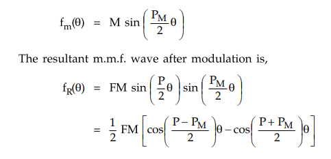
Thus the resultant wave is equivalent to two waves having two separate number of poles as,
Pl
= P - PM and P2 = P + PM
This
is called suppressed carrier modulation.
If
we succeed in suppressing one of the two poles then there exists rotating
magnetic field with number of poles as P1 or P2. And
while suppressing, the method can be used such that the resultant number of
poles retained is as required from the speed point of view.
Now
if the three stator windings are placed such that angle between their phase
axes is (2π/3) r radians where r is an integer which is not divisible by 3 then
the phase axes angle for modulated poles is given by,
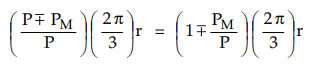
Now
to suppress one of the two poles, the angle between its phase axes must be
multiple of 2π.
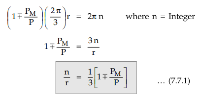
So
if r and n are selected so as to satisfy one of the above relations, then
either P1 or P2 get suppressed and field corresponding to
other pole exists. So speeds corresponding to P poles without modulation and
corresponding to either P1 or P2 with modulation, can be
achieved. The negative sign in equation (7.7.1), gives suppression of P1
and existence of P2 = P + PM while positive sign in equation (7.7.1),
gives suppression of P2 and existence of p1 = P - PM
poles.
For
example, stator has 8 poles while values of n and r are selected as 1 and 4
respectively, r is not divisible by 3.
Let
poles of modulating function PM are 2.
From
equation (7.7.1) we can see that,
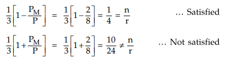
Thus
P1 gets suppressed and we get poles P2 = P + PM
= 10.
So
two speeds corresponding to P and P2 can be obtained.
Similarly
if the poles of modulating function PM are 4 and n and r are selected as 1 and
2 then, 1
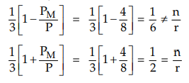
In
this case P2 gets suppressed and we get poles P1 = P - PM
= 4
This
method is advantageous as it reduces the size to a great extent and hence cost
of the machine.
The
limitation that it can be used only for squirrel cage motors still continues.
Key Point Practically the
rectangular wave is used for modulation. This is achieved by dividing stator
coil into PM groups and then by dropping alternate group, other
groups are connected in series opposition.
Example
7.7.1 A 50 Hz induction motor uses a pole amplitude
modulation method to control the speed. The stator has 16 poles while the pole
modulating function has 4 poles. At what two speeds motor can run ?
Solution
:
P
= 16 and PM = 4
Let n = 1 and
r = 4
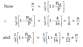
Thus
as first equation with negative sign is satisfied, the P1 poles are
suppressed. So two possible speeds of motor are
corresponding to P = 16 and P2 = P + PM = 20.
Ns
= 120 f / P = 120 × 50 / 16 = 375 r.p.m
Ns
= 120 f / P2 = 120 × 50 / 20 = 300 r.p.m
Review Questions
1. How the speed of the induction motor is controlled by
controlling the number of stator poles ?
2. Explain the pole amplitude modulation method.
3. Explain the pole changing method of controlling the speed of
induction motor. AU : May-13, Dec.-14,17, Marks 4
4. Explain in detail the speed control methods of induction
motor. AU ; May-16, Marks 8
5. Explain the speed control methods of a three phase induction
motor. AU ; Dec.-16,May-18, Marks 16
Electrical Machines II: UNIT IV: Starting and Speed Control of Three Phase Induction Motor : Tag: Engineering Electrical Machines - II : Three Phase Induction Motor - Controlling Number of Poles
Related Topics
Related Subjects

Electrical Machines II
EE3405 Machine 2 EM 2 4th Semester EEE Dept | 2021 Regulation | 4th Semester EEE Dept 2021 Regulation