Electrical Machines: Unit V: Autotransformer and Three Phase Transformer
Conversion from Three Phase to Two Phase (Scott Connection)
Transformer
• With the help of Scott connection, proposed by C.F. Scott, it is possible to obtain 2 phase supply which is required for furnaces or even three phase load can be driven from the available 2 phase supply source. The Scott connection which is serving this purpose is shown in the Fig. 7.6.1.
Conversion
from Three Phase to Two Phase (Scott Connection)
•
With the help of Scott connection, proposed by C.F. Scott, it is possible to
obtain 2 phase supply which is required for furnaces or even three phase load
can be driven from the available 2 phase supply source. The Scott connection
which is serving this purpose is shown in the Fig. 7.6.1.

•
This connection uses two transformers with different ratings. But identical
transformers with suitable tappings may also be used for the interchangeability
and provision of spares. One of the transformers having 50 % tapping is called
main transformer and other one having 86.6 % tapping is called teaser
transformer. If the secondaries of the two transformers are connected as shown
in the Fig. 7.6.1 then two phase, three wire system is obtained.
•
One end of the primary winding of the teaser transformer is connected to the
centre tapping provided on the primary winding of the main transformer. The two
ends of the primary winding of the main transformer and 86.6 % tapping point on
the teaser transformer is connected to a balanced three phase supply. The
voltage per turn is same both in primary of both main and teaser transformer.
With the equal number of turns on secondaries of both the transformers, the
secondary voltage will be equal in magnitude which results in symmetrical 2
phase system.
•
The same connection drawn slight differently is shown in the Fig. 7.6.2.

•
The main transformer primary winding consists of N1 turns connected
between lines Y and B of a symmetrical three phase supply. VRY' VYB
and VBR are all line voltages. Hence VRY = VYB
= VBR = VL But RO being the altitude of the equilateral
triangle, the voltage VRO is √3 / 2 VL. The voltage per
turn will be same in primaries of both the transformers if number of turns
between R and O are (√3/2) N1. With this then the terminal voltages
on the secondary windings having same turns will be equal in magnitude and have
a phase difference of 90° between them.
•
The point O is not the neutral point of 3 phase supply voltage as its voltage
with respect to any line is not VL / √3. N is the neutral point
shown in Fig. 7.6.3. Voltage VRN is nothing but VL / √3
whereas VRO is (√3/2) VL. Hence the voltage between N and
O will be

•
Since 0.29 is one third of 0.866, N divides the teaser winding RO in the ratio
2: 1.
•
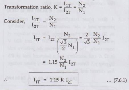
Now let us consider the unity power factor load. The teaser secondary is
supplying a current of I2T Neglecting the magnetizing current I0
we have,
Transformation
ratio,
'•
Each half of the primary winding of the main transformer carries current of I1m
consisting of two parts.
i)
First part balances the main secondary current I2M

ii)
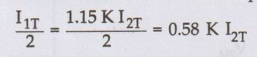
The second part is equal to one half of the teaser primary current i.e. ½ I1T
•
The main transformer primary winding forms a return path for the teaser primary
current which is divided into two halves at point O in either direction.
The
current in each half is equal to
This
current is shown in the Fig. 7.6.4.

•
Thus the phase R supplies current I1T which is divided into two
equal parts and is flowing in the main transformer in the opposite directions.
Thus the line currents on the primary side are vectorially given by,
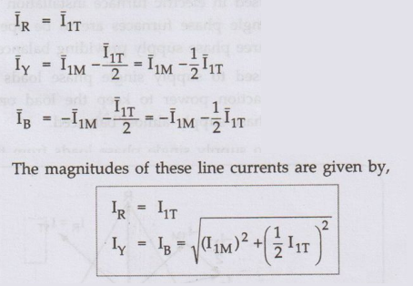
•
The currents in the lines Y and B are obtained vectorially. The teaser
transformer currents flowing in the two halves of the primary winding of the
main transformer in the opposite direction and have no magnetic effect on the
core and does not take part in balancing the secondary ampere turns of the main
transformer. Thus when two phase load of unity power factor is balanced then
three phase side is also balanced.
•
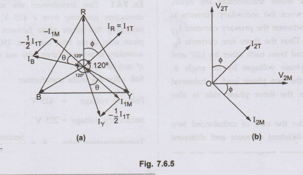
Now let us consider balanced two phase load at a lagging p.f. of cos ϕ. The
corresponding phasor diagram is shown in the Fig. 7.6.5. The three phase side
is again balanced as the currents drawn from the three phase system are equal
balanced and lag by angle ϕ with respect to their respective phase voltages.
This can be shown mathematically.
• Let us consider the equal currents at a power factor of cos ϕ lagging from secondary side,

Thus
all the currents in the primary side are equal in magnitude.
We
have from the phasor diagram,

•
Since the power factors of the loads for the main transformer and the teaser
transformer are equal, the phase angle between the secondary currents is also
90°. The angle between the primary currents I1T and I1M
is also 90°. Thus the three line currents IR', Iy and IB
are displaced from each other by 120° and lag the respective phase voltages by
an angle . This proves that if the two phase load is balanced then the loading
on the three phase side is also balanced.
•
Now we will consider the case of unbalanced two phase load having different
currents and different power factors. The phasor diagram for this case can be
constructed in a similar manner. It is shown in the Fig. 7.6.6.

1. Applications of Scott Connection
•
The Scott connection is used for:
1.
Linking three phase system with two phase system with the flow of power in
either vilah direction.
2.
Used in electric furnace installation where two single phase furnaces are to be
operated from three phase supply providing balanced load.
3.
Used to supply single phase loads as electric traction power to keep the load
on the three phase supply almost balanced.
4.
To supply single phase loads from three phase system for better balancing of primary
power system.
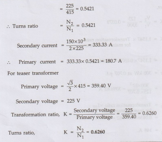
Ex. 7.6.1 Two
transformers are required for a Scott connection operating from a 415 V, 3
phase supply for supplying two single phase furnaces 225 V on the two phase
side. If the total output is 150 kVA, calculate the secondary to primary turns
ratio and the winding currents of each transformer.
Sol. :
For
the main transformer
Primary
voltage = 415 V
Secondary
voltage = 225 V
Transformation
ratio, K = Secondary voltage / Primary voltage
Ex. 7.6.2 In a Scott connection, calculate
the values of line currents on the 3 phase side, if the loads on 2 phase side
are 300 kW and 400 kW, both at 125 V and 0.707 p.f. and the three phase line
voltage is 3300 V. The 300 kW load is on the leading phase of the 2 phase side.
Neglect the losses.
Sol. :

Primary line voltage =3300 V
Secondary
voltage = 125 V
Load
carried by teaser secondary = 300 kW at 0.707 p.f.
Load
carried by main secondary = 400 kW at 0.707 p.f.
Transformation
ratio for main transformer,

Power
supplied by teaser transformer = 300 kW at 0.707 p.f.
Secondary current in teaser transformer, I2T = 300 × 103 / 125 × 0.707= 3394.62 A

Review Questions
1. With the help of
phasor diagram explain how 2 phase supply can be obtained from 3 phase supply
using Scott connection.
2. Two electric furnaces are supplied with single-phase circuit at 100 V from a 3-phase, 13,750 V supply by means of two single-phase Scott-connected transformers with similar secondary windings when the load on main transformer is 625 kW and on the teaser is 1000 kW, what current will flow in each of 3-phase lines at unity power factor?
[Ans.: IR=83.9 A, ly = lB=61.83
A]
Electrical Machines: Unit V: Autotransformer and Three Phase Transformer : Tag: : Transformer - Conversion from Three Phase to Two Phase (Scott Connection)
Related Topics
Related Subjects

Electrical Machines I
EE3303 EM 1 3rd Semester EEE Dept | 2021 Regulation | 3rd Semester EEE Dept 2021 Regulation