Electrical Machines: Unit II: D.C. Generators
Critical Field Resistance in D.C. Shunt Generator
Consider the magnetisation characteristics of a d.c. shunt generator shown in the Fig. 3.29.1.
Critical
Field Resistance in D.C. Shunt Generator
AU: Dec.-05
•
Consider the magnetisation characteristics of a d.c. shunt generator shown in
the Fig. 3.29.1.
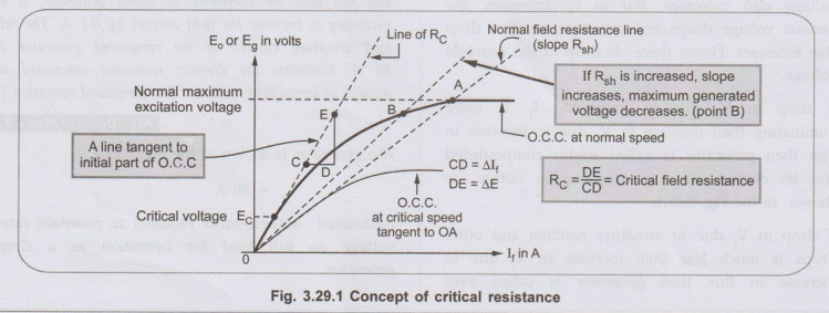
• The Fig. 3.29.1 shows that generator voltage builds in step till point A. This point is intersection of field resistance line with the Open Circuit Characteristics (O.C.C.). The voltage corresponding to point A is the maximum voltage it can generate. If the slope of field resistance line is reduced by decreasing thebuild will be higher than that corresponding to point A. Similarly if the slope of field resistance line is increased by increasing the field resistance, the maximum voltage generator can build will be less than that corresponding to point A i.e.corresponding to point B.
•
If now the slope of the field resistance line is increased in such a way that
it becomes tangential to the lower part of the open circuit characteristics.
The voltage corresponding to this point is Ec. This voltage is just sufficient
to drive the current through field resistance so that cumulative process of
building the voltage starts. This value of field resistance is called the
critical resistance denoted as Rc, of the shunt field circuit at given speed.
Key Point:
If field circuit resistance is more than RC at start then induced
e.m.f. fail to drive current through field circuit and generator fails to
excite at given speed.
Thus
we can define critical resistance as that resistance of the field circuit at a
given speed at which generator just excites and starts voltage building while
beyond this value generator fails to excite.
The
critical resistance is the slope of the critical resistance line.
ஃ
Rc = ΔΕ / ΔΙf =
DE / CD = tan θ
•
Similar to the critical resistance there is a concept of critical speed NC.
We know that E ∞ N. As speed decreases the induced e.m.f. decreases and we get
O.C.C. below the O.C.C. at normal speed. If we go on reducing the speed, at a
particular speed we will get O.C.C. just tangential to normal field resistance
line.
Key Point:
This speed at which the machine just excites for the given field circuit
resistance is called the critical speed of a shunt generator denoted as NC.
1. Practical
Determination of RC
•
Generally data for plotting the open circuit characteristics is given. Plot the
characteristics is given. Plot the characteristics on the graph paper to the
scale.
•
Draw the tangent, to the initial part of this O.C.C. then the slope of this
line is the critical resistance for the speed at which the data is given.
Key Point:
If speed changes, then the O.C.C. changes hence the value of RC
changes.
Now
if Rc is asked at speed N2, while data for O.C.C. is given at N1.
It is known that,

Key
Point: Generate the data for O.C.C. at new speed and repeat the procedure to
obtain Rc.
2. Critical Speed NC
•
It is known that as speed changes, the open circuit characteristics also
changes, similarly for different shunt field resistances, the corresponding
lines are also different.
Key Point:
The speed for which the given field resistance acts as critical resistance is
called the critical speed, denoted as NC.
•
Thus if the line is drawn representing given Rsh then O.C.C. drawn for such a
speed to which this line is tangential to the initial portion, is nothing but
the critical speed NC.
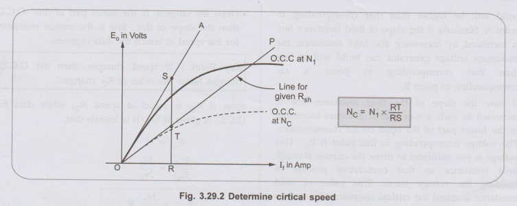
Graphically
critical speed can be obtained for given Rsh. The steps are,
1.
Drawn O.C.C. for given speed N1.
2.
Draw a line tangential to this O.C.C. say OA.
3.
Draw a line representing the given Rsh say OP.
4.
Select any field current say point R.
5.
Draw vertical line from R to intersect OA at S and OP at T.
6.
Then the critical speed NC is,
While
RT /RS = NC/ N1 i.e NC = N1 RT / RS
Ex. 3.29.1 The following figures give the open circuit characteristic of a d.c. shunt generator running at 300 r.p.m.

Determine the voltage to which
machine will excite if field circuit resistance is 40 ohm and run at 375 r.p.m.
i) What additional resistance would
have to be inserted in the field circuit to reduce the voltage to 200 V at 375
r.p.m.
ii) Without additional resistance
determine the load current supplied by the generator when its terminal voltage
is 200 V. Ignore armature reaction and assume speed to be constant. Armature
resistance is 0.4 ohm.
Sol. For the shunt generator

Construct
the new table for open circuit characteristics at N2 = 375 r.p.m,
using above relation.

The
graph is shown in the Fig. 3.29.3.
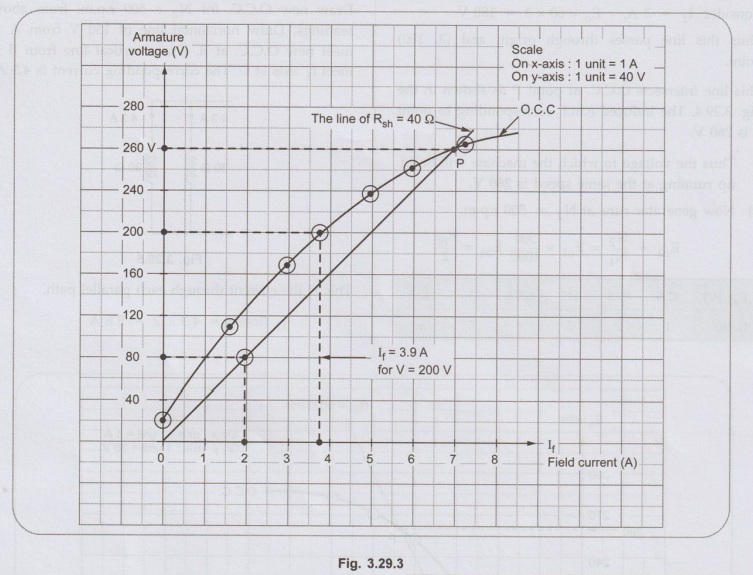
Draw
the line corresponding to Rsh = 40 Ω . Το draw this line, consider
the equation of line as y = mx which passes through origin and slope m which is
nothing but Rsh
V
= Rsh If …. For line of Rsh
So
two point are, (0, 0) and (2, 80). From these points draw the straight line
till it intersects O.C.C. at point P as shown. The voltage corresponding to
point P is 260 V. Thus machine will excite to 260 V if
Rsh
= 40 Ω and speed 375 r.p.m.
i.
To have V = 200 V, find If from the graph which is, If =
3.9 A

Ex. 3.29.2 A shunt generator running at a speed of 1000 r.p.m. gave the following magnetization curve:

If the field circuit resistance is
60 Ω, determine
i)The voltage to which the machine
will build up running at the same speed.
ii) The value of the field
regulating resistance if the machine is to build up to 130 V, when its field
coils are grouped into two parallel circuits and generator is run at 500 r.p.m.
AU: Dec.-05, Marks 16
Sol. :
Draw the open circuit characteristics on the graph paper from the given data.
Draw
the line corresponding to Rsh = 60 Ω For this, consider an equation of line y =
mx, passing through the origin.

Consider
If = 3 A Eo = 60 × 3 = 180 V
Thus
this line passes through origin and (3,180) point
This
line intersects O.C.C. at point P as shown in the Fig.3.29.4. The induced
e.m.f. corresponding to point P is 260 V
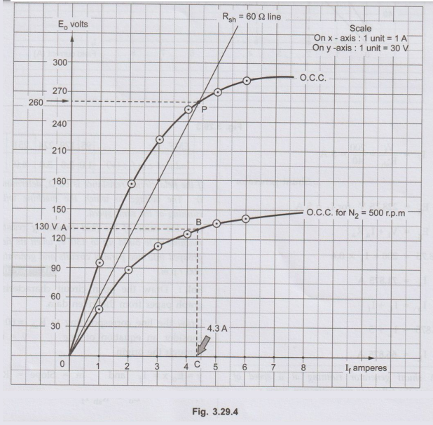
i)
Thus the voltage to which the machine will build up running at the same speed
is 260 V.
ii)
Now generator runs at N2 = 500 r.p.m.

Draw
new O.C.C. for N2 = 500 r.p.m. from above readings. Draw horizontal line of 130
V from A to meet new O.C.C. at B. Draw vertical line from B to meet lf axis at
C. The corresponding current is 4.3 A.

The
original 60 Ω Rsh is divided into two groups i.e. each of 30 Ω and then
connected in parallel.
Field
regulating resistance = 15.1162 – 15
=
0.1162 Ω
Review Questions
1. Explain the
concept of critical field resistance and lacritical field.
2. The magnetization
curve of a d.c. shunt generator running at 1000 r.p.m. is as follows:

Find i) The value of
field resistance to give 240 V on no-load ii) The spezed at which the generator
just fails to build up. [Ans.: 106.67 Ω 2,
660.38 r.p.m.]
3. The open-circuit characteristic of a shunt
o generator at 800 r.p.m. gives:

Find graphically the
critical resistance of shunt field circuit. If the field circuit resistance is
changed to 75 Ω, what will be the critical speed for the machine to build up? [Ans. : 586.67
r.p.m]
Electrical Machines: Unit II: D.C. Generators : Tag: : - Critical Field Resistance in D.C. Shunt Generator
Related Topics
Related Subjects

Electrical Machines I
EE3303 EM 1 3rd Semester EEE Dept | 2021 Regulation | 3rd Semester EEE Dept 2021 Regulation