Electric Circuit Analysis: Unit III: Transient Response Analysis
D.C. Transients in RC Circuit
Steps, Worked Example Solved Problems
Electric Circuit Analysis: Unit III: Transient Response Analysis : D.C. Transients in RC Circuit : Worked examples
WORKED EXAMPLES
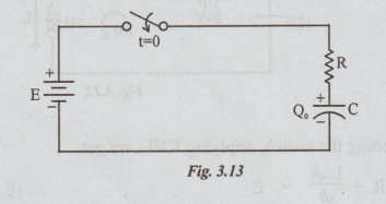
2. Case 2: (a) R-C Transients (Charging)
Consider
the R-C series combination. A DC voltage E is applied to this combination
through the switch as shown in fig. 3.13.
Let
Q0 = initial charge on the capacitor. So, the initial voltage on the
capacitor = V0 = Q0
/ C.Let the polarities of Vo be as shown:
After
1 seconds of closing the switch, applying Kirchoff's voltage law to the circuit
we get,

[Note: If the polarities of Vo
are opposite to that shown in the figure, then replace Vo in the above equation
by -Vo]
In
the present case let us assume that the initial charge on the capacitor is 0.
Hence V1 = 0. Substituting Vo = 0 in equation (iii) we get, the
final equation as
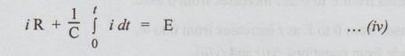
Taking
Laplace transform on both sides, we get
E
/ R is the initial value of the current denoted by I, RC is called time
constant denoted by λ.
Therefore,
we can express the charging current as,
i
(t) = I e –(t/λ) ... (vi)
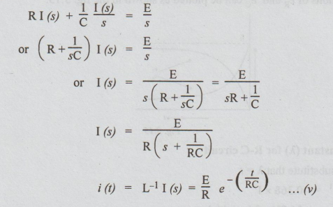
This
charging current seems to be exponentially decreasing as is observed from the
equation (vi).
The
initial current = the value of i when (t = 0) = I
The
steady current = the value of i when (t = ∞) = 0
The
variation of the current with time is graphically shown in the fig. 3.14.
The
transient voltages eR and eC are obtained as below:

eR
exponentially decreases from E to 0 as t increases from 0 to ∞.
eC
exponentially increases from 0 to E as t increases from 0 to ∞.
These
observations are made from equations (vii) and (viii).
Graphically,
the variations of e, and ec can be plotted as shown in the fig. 3.15.

Definition
of Time - Constant (λ) for R-C circuit
In
the equation (viii), substitute that λ = t.
Then
i = I × e-1 = 0.368 × I
=
36.8% of the initial current
Thus,
the time constant for the RC circuit is the time during which the current falls
to 36.8% of initial current.
[Note:
We can also get e by the formula 
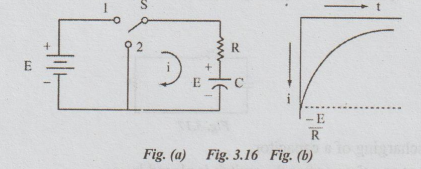
3. Case (b) R - C Decaying Transient (Discharging)
Consider
the circuit of the fig. 3.16. The switch has been in position 1 for sufficient
time to establish steady state condition. Let this switch be moved to position
2 at the instant t = 0.
Under
steady state condition, the capacitor is fully charged. The voltage across C is
E with the polarities as shown in the fig.3.16, The differential equation of
the circuit is,
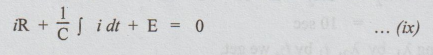
Taking
Laplace transform and rearranging the terms, we get
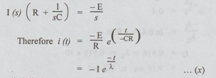
This
current is called discharging current.
The
current curve is as shown in the fig. 3.16.
WORKED EXAMPLES
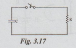
Example 7 A resistance R and a 2uF capacitor are connected in series across a 200V direct supply. Across the capacitor is a neon lamp that strikes at 120V. Calculate R to make the lamp strike 5 sec after the switch has been closed. If R = 5M 2, how long will it take the lamp to strike?
Solution: Case (i):

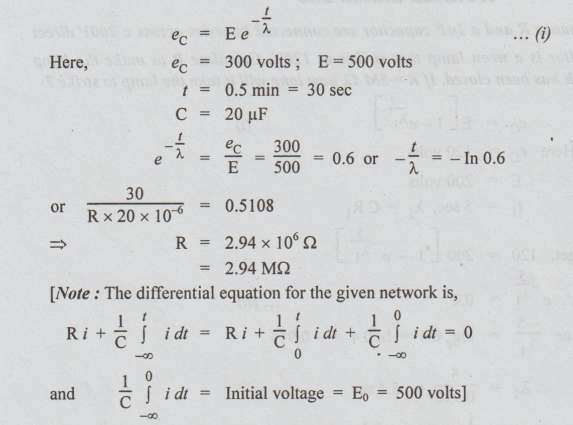
Example 8 A resistor is connected across the terminals of a 20 uF capacitor which has been previously charged to a.p.d. of 500V. If the p.d. falls to 300V in 0.5 min, calculate the resistance in megaohms.
Solution :
This is case of discharging of a capacitor.
The p.d. across C at any time t after the switch is closed is,
We can proceed to solve this equation by Laplace transform method. It yields the final solution which we already obtained.]
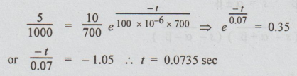
Example 9 Find how long it takes after the key is closed before the total current from the supply reaches 25 mA, when V = 10V, R1 = 500 2, R2 = 700 2 and C = 100 μF.
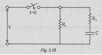
Solution:
Let i1 = the current through R1
i2 = current (charging current)
through the capacitor after t seconds of closing the switch.
I1 = V / R1 = 10 / 500 A = 20 mA
It is constant.
Given that Total current = i = 25 mA
By applying KCL,
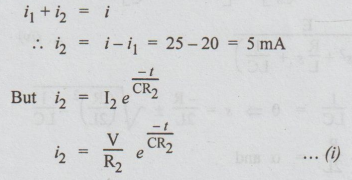
Substituting the known values in equation (i), we get
Electric Circuit Analysis: Unit III: Transient Response Analysis : Tag: : Steps, Worked Example Solved Problems - D.C. Transients in RC Circuit
Related Topics
Related Subjects

Electric Circuit Analysis
EE3251 2nd Semester 2021 Regulation | 2nd Semester EEE Dept 2021 Regulation