Electric Circuit Analysis: Unit III: Transient Response Analysis
D.C. Transients in RLC Circuit (with Step Input Voltage)
Worked Example Solved Problems
Electric Circuit Analysis: Unit III: Transient Response Analysis : Worked examples
4. R-L-C Transients (with Step Input Voltage)
Applying
KVL to the circuit, we get

We
can take partial fractions to the right hand side expression. On inverse
laplace transform, i (t) can be evaluated.
Based
on the value of discriminant there are three possibilities of solution for i
(t).
Case
(i): If (R/2L)2 > 1/LC The two roots are
real and distinct.
We
may write I (s) as
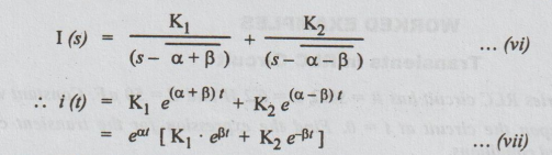
This
current is said to be over damped.
Case
(ii): If the discriminant is zero, (R/2L)2 = 1/LC
The
roots are real and equal.
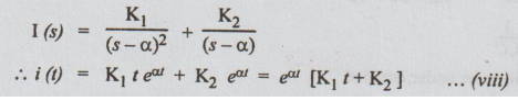
The
solution is critically damped case.
Case
(iii): The discriminant is negative, (R/2L)2
< 1?LC
The
roots are complex conjugate. Now let us define that,
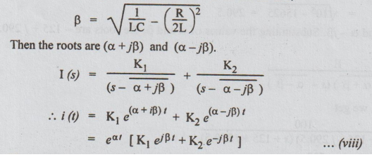
The
above expression can be written as,
i
(t) = eɑt [A cos βt + B sin βt] … (ix)
The
solution shows that the current is oscillatory and at the same time decays in a
short time [since a is always negative.]
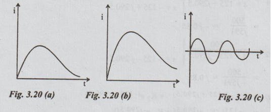
The
solution is said to be under damped. The response shown by equations (vii),
(viii) and (ix) are represented in the fig. 3.20 (a), (b) and (c) respectively.
WORKED EXAMPLES
Transients in RLC Circuit
Example 10 A series RLC circuit has R = 502, L = 0.2 H and C = 50 μF. Constant voltage of 100V is impressed upon the circuit at t = 0. Find the expression for the transient current assuming initially relaxed conditions.
Solution:
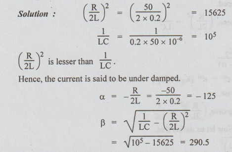
Hence, the current is said to be under damped.
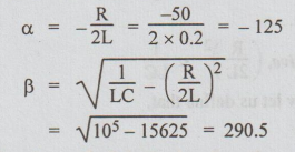
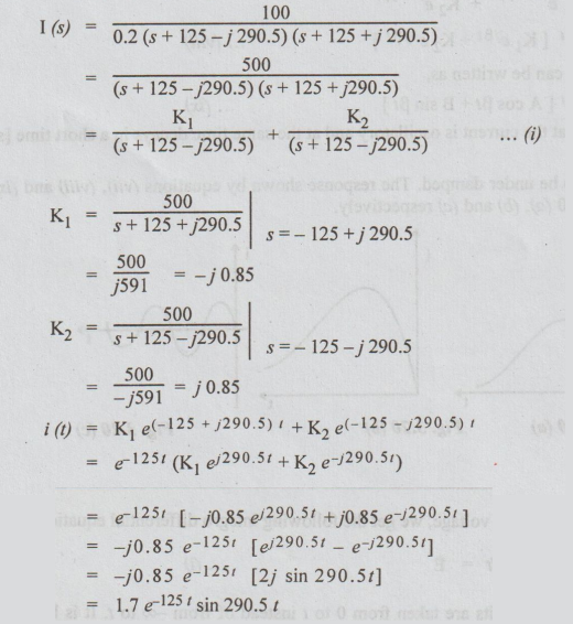
The roots are a + jβ and a -jβ. Substituting the values of a and β, the roots are - 125 + j 290.5 and 125j 290.5.
Example 11 A series RLC circuit with R = 202, L = 10H, and C=5F has a constant voltage V=100V applied at t=0. Find the current response in the circuit, assuming zero initial condition.
Solution :

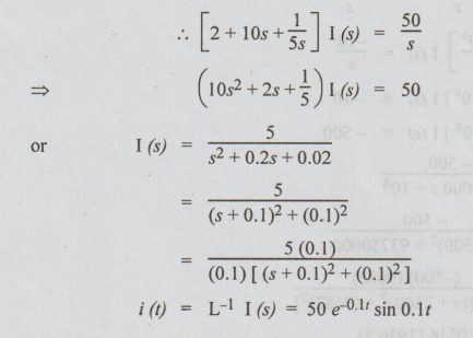
Example 12 A series RLC circuit with R = 3002, L = 1H, and C = 100 x 10° F has a constant voltage of 50V applied to it at t=0. Find the maximum value of current (assume zero initial condition.)
Solution: Let us solve this problem from the first principles.
After t seconds of applying the voltage, we get the following integro differential equation.
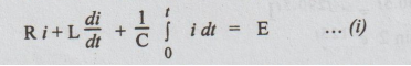
In the above equation, the limits are taken from 0 to t instead of from co to t. It is because, the initial voltage across the capacitor = V0
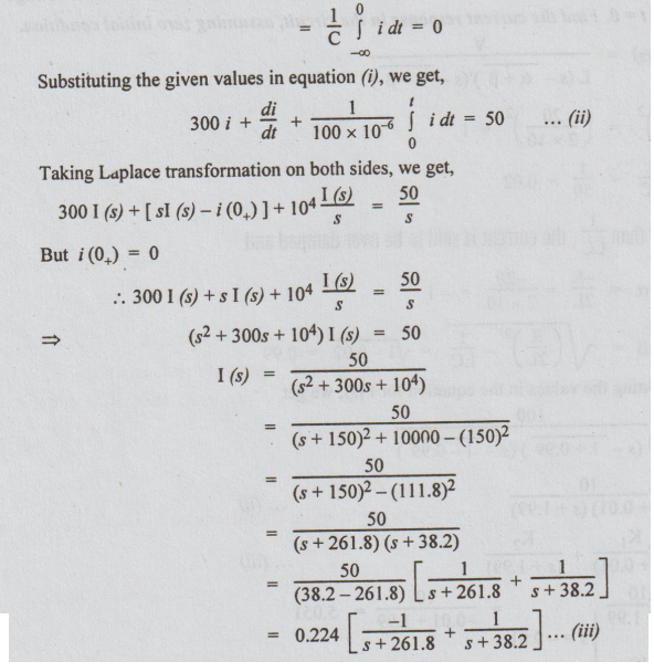
Taking inverse Laplace of equation (iii), we get

It is required to find the maximum value i(t)
Equating di/dt to 0, we get the value of t. At this value of t, if d2i / dt2 is negative then i (t) is maximum.
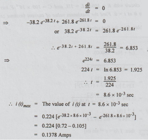
[Note: d2i / dt2 is not evaluated at t = 8.6 milli seconds. The student can find this second derivative at t = 8.6 ms and may observe that it is negative.]
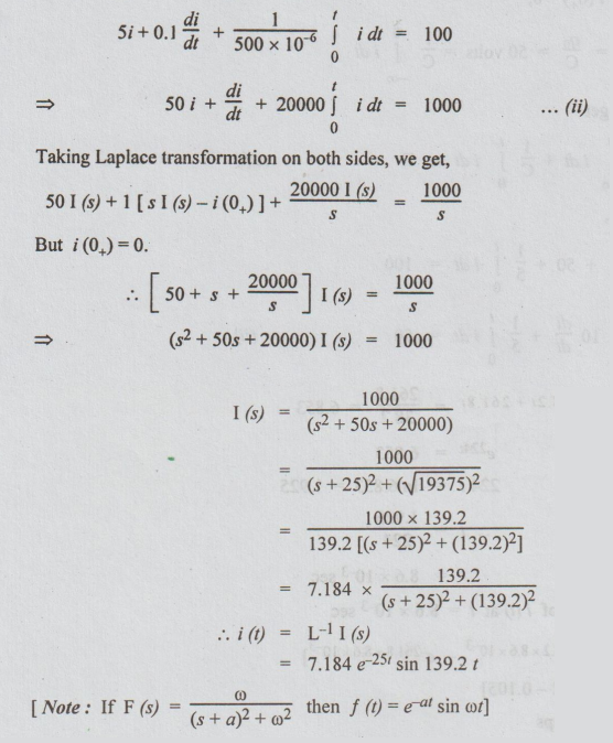
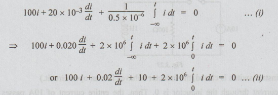
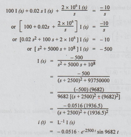
Example 13 A series RLC circuit with R = 52, L = 0.1 H and C = 500 x 106 F has a D.C. voltage of 100V applied at t = 0 through a switch. Find the resulting current transient.
Solution: Let us solve this problem starting from the formation of integro differential equation. It is obtained by applying KVL.
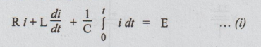
In the above equation the initial voltage across the capacitor is assumed to be 0. That is why the limits are 0 to t.
Substituting the values given, we get,
Example 14 A step voltage V (t) = 100 u (t) is applied to a series R-L-C circuit with L = 10 henrys, R = 2Ω, and C = 5 farads. The initial current in the circuit is zero but there is an initial voltage of 50V on the capacitor in a direction which opposes the applied source. Find the expression for the current in the circuit.
Solution :

Taking Laplace Transform and substituting i (0) = 0.
[Note: Again if F (s) = ω / (s+a)2 + ω2 then F (t) = et sin at formula is used. Instead we can solve for i (t) by partial fractions.]
Example 15 For a source-free RLC series circuit, the initial voltage across C is 10V and the initial current through L is zero. If L = 20mH, C=0.5 μF and R = 100Ω, evaluate i (1).
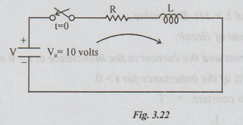
Solution: Initial conditions given i (0+) = 0
V0 = q0 / C = 10
By applying KVL, we get the following equation,
Taking Laplace Transform on both sides,
Example 16 A constant current source of 10A is suddenly applied at t=0 on R-L parallel circuit with R = 100Ω and L = 1H. Determine:
(i) the time constant of circuit,
(ii) the voltage across and the current in the inductance at t = 0 and t → ∞, and
(iii) the voltage V (t) of the inductance for t > 0.
Solution: (i) Time constant = T
= L/R
= 1/100
= 0.01 sec
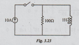
(ii) At t=0, (i.e., the instant switch is closed, the inductor behaves like an open circuit.)
Hence, at t = 0, the current through the inductor is 0. Then, the entire current of 10A passes through the resistor. The voltage across the resistor is equal to IR = 10 × 100 = 1000V.
The inductor is in parallel with the resistor. Hence, the voltage across it will also be equal to 1000V.
At t = ∞, the inductor behaves like a short circuit. Hence, the current through the inductor becomes 10A. The current through the resistor reduces to 0. It leads to voltage to be zero across both resistor and inductor.
(iii) Let at any time t, i (t) be the current through the inductor. It is required to find the expression for i (t) and hence voltage across the inductor.
By applying KCL, the current through the resistor = 10-i (t).
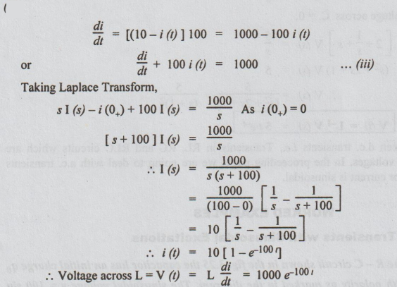
The voltage across the inductor = L di/dt = 1 di/dt = di/dt … (i)
By Ohms Law voltage across the resistor = [(10 - i (t)] × 100 ... (ii)
As inductor and resistor are in parallel, voltage must be same, Hence, equating equation (i) and (ii)
Example 17 For the circuit shown in fig. 3.24, find the voltage across the resistor 0.5Ω when the switch, S, is opened at t = 0. Assume that there is no charge on the capacitor and no current in the inductor before switching.
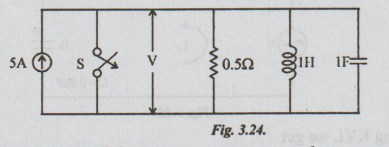
Solution: [Note: For solving parallel circuits in transients, we have to apply KCL. It yields the following equation.]

Till now we have seen d.c. transients i.e., Transients in RL, RC and RLC circuits which are energised by step input voltages. In the proceeding pages we are going to deal with a.c. transients where the input voltage or current is sinusoidal.
Electric Circuit Analysis: Unit III: Transient Response Analysis : Tag: : Worked Example Solved Problems - D.C. Transients in RLC Circuit (with Step Input Voltage)
Related Topics
Related Subjects

Electric Circuit Analysis
EE3251 2nd Semester 2021 Regulation | 2nd Semester EEE Dept 2021 Regulation