Electric Circuit Analysis: Unit III: Transient Response Analysis
DC transients
Transient Response Analysis
Here we have three types of circuits. In each case the voltage applied (excitation) is assumed to be step voltage denoted by Eu (t). u (t) is the unit step voltage.
DC TRANSIENTS
Here
we have three types of circuits. In each case the voltage applied (excitation)
is assumed to be step voltage denoted by Eu (t). u (t) is the unit step
voltage.
1.
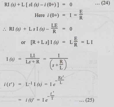
(a) Case 1: (a) R-L Transients: (Rise of Current)
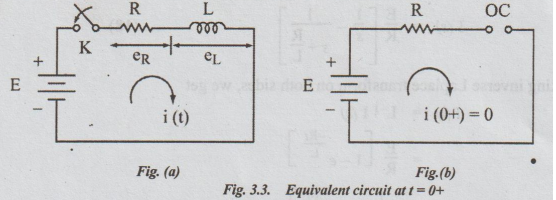
Let
the R – L series combination
be impressed upon the d.c. voltage E by closing the switch K. Assume that the
current through the inductor before closing the switch is zero. Let K be closed
at the instant t = 0.
The
equivalent circuit at t=0+ is shown in fig. 3.3 (b). The inductor is shown as
open circuit. Hence i (0-) = i(0+) = 0.
Applying
KVL to the circuit in fig. 3.3 (a), after t seconds of closing K,
we
get, Ri + L di / dt = E … (15)
Taking
Laplace Transformation on both sides, we get
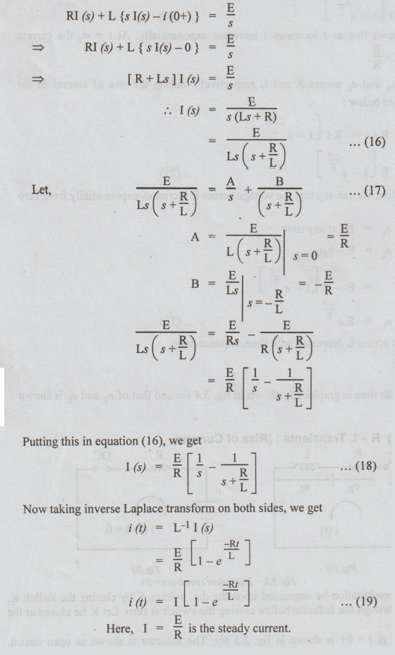
Steady
current is thevalue of I (t) for t = ∞
L/R
is called time constant of the RL circuit and is denoted by T.
Hence
equation (19) can be written as
I
= I [I – e –t/T] … (20)
The
above equation shows that as t increases i increases exponentially. At t = ∞,
the current reaches steady state value I = E / R.
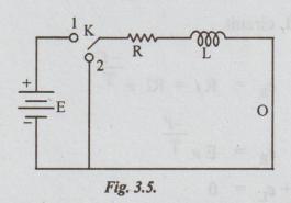
The
transient voltage eR and eL across R and L respectively,
during the rise of current in the inductive can be expressed as below:
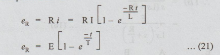
From
the above expression, we can say that the voltage across R increases
exponentially from zero to E, during rise of current.
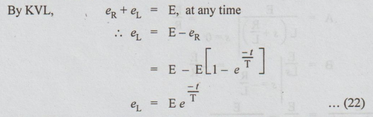
It
shows that the voltage across L decreases with time, exponentially
[Note:
eL = - L di / dt]
The
variation of i (t) with time is graphically shown in fig. 3.4 (a) and that of in
fig. 3.4 (b).
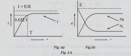
Definition
of time constant T for RL circuit
Substituting
T = t in equation (20), we get
i
= I (1 – e-1)
=
0.632 I
=
63.2% of I
Thus
the time constant of RL series circuit is defined as the period during which
the current rises to 63.2% of its final value (OR steady value).
(b)
RL-Decaying Transients
Assume
that the switch K is kept connected to position 1 for sufficiently longer
period. Then the current reaches steady state value given by I = E / R. After this instant, let the switch be
moved from position 1 to position 2. Let this instant be taken as t = 0. After
t' seconds of closing the switch to position, applying KVL,
Ri+
L di / dt’ = 0 … (23)
Taking
Laplace Transformation on both sides, we get
Thus
i decays exponentially from I to zero, as t' increases from zero to infinity.
The variation of i (t') with t' is graphically shown in fig. 3.6.
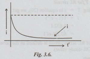
Decaying
current in an R - L circuit.
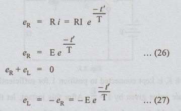
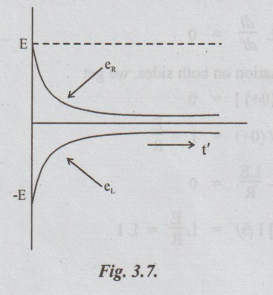
The
variation of er and e, with t' is graphically shown in fig. 3.7.
Electric Circuit Analysis: Unit III: Transient Response Analysis : Tag: : Transient Response Analysis - DC transients
Related Topics
Related Subjects

Electric Circuit Analysis
EE3251 2nd Semester 2021 Regulation | 2nd Semester EEE Dept 2021 Regulation