Basic Civil & Mechanical Engineering: UNIT III: a. Foundations or substructures
Deep foundations
Uses, Types, Advantages, Classification
The design and construction of Deep Foundations is a challenging job for a civil engineer. 'A foundation is said to be a Deep Foundation, when its depth is more than the width of the foundation.
DEEP FOUNDATIONS
The
design and construction of Deep Foundations is a challenging job for a civil
engineer. 'A foundation is said to be a Deep Foundation, when its depth is more
than the width of the foundation. Deep foundations transmit the load of a super
structure through weak soils to strong soil beds or rock beds available at
great depth.
Uses:
When the soil available at a reasonable depth of less than, say, 3 to 6 meters
is not having the desired bearing capacity, deep foundation is used.
Types
of Deep Foundations
1.
Piles, 2. Piers and 3. Well
1. PILE FOUNDATIONS
Pile
In
some cases, the soil at a site may have a very low bearing capacity for great
depths (6 m or more). It may be impracticable to improve the strength of such
soils by compaction. In such cases, a pile foundation is used to transmit the
weight of the structure to a stratum of good strength or to rock.
Pile
is a R.C.C. column member (or a timber column member). It is driven into the
ground to a suitable depth. It transfers the load on it to a deeper and harder
layer of the soil or rock.
Generally,
part of the load on the pile is taken by friction offered by the surrounding
soil. The remaining part of the load is transmitted to the hard stratum up to
which it is sunk.
Piles
are installed in groups by driving by hammer or by any other suitable means.
The pile groups may be subjected to vertical loads or horizontal loads or a
combination of vertical and horizontal loads.
Advantages:
A
pile occupies less space. It is not liable to big settlements.
1.Usage
of Piles
1.
When loads to be transmitted to the sub-soil are very large and concentrated.
2.
Providing Mat foundation may not be economical.
3.
When foundation soil is loose and hard stratum is available at about 10 m
depth.
4.
When considerable rise or fall of sub-soil water level occurs seasonally.
5.
When the structure is tall and heavy, but deep bed of sandy soil is available.
6.
When there are possible future constructions of deep sewers / canals close to
the site.
7.
When the foundation is to be carried below the maximum possible scour depth.
8.
To prevent any excessive settlement of the soil.
9.
The top soil is of expansive nature like Black Cotton Soil, etc.
10.
Sea-shore or river bed constructions or foundations in moist areas.
2. CLASSIFICATION OF PILES
Piles
are classified on the basis of
1.
Material Compositions
2.
Installation Methods
3.
Functions or Uses
4.
Ground Effects
1.
Classification Based on Material Compositions
Ground
Based on Material Composition, piles are classified as Steel Piles, Concrete
Piles, Timber Piles and Composite Piles.
(i)
Steel Piles
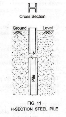
Steel
piles are made in three forms: Rolled Steel H-Section Piles, Box Piles and Tube
Piles. There can be no restriction on length due to high strength of steel.
However,
steel piles may be affected by corrosive agents like salt, moisture or acid. To
prevent the corrosion of piles, the thickness is increased or encased in
concrete or chemical coating with paint is applied.
See
Fig. 11. In this, H-Section Pile having wide flanges is used. The pile projects
slightly above the Ground Level and functions as a Column. Due to its small
cross-section, it can be driven into the soil easily.
Box
Pile is rectangular or octagonal. It is filled with concrete. When H-Section
pile is difficult to be driven, box file is preferred. Tube Pile can be sunk
into the ground easily. It is filled with concrete.
(ii)
Concrete Piles
Concrete
Pile is stronger and more durable than steel piles. It is not subjected to
decay by termite like timber piles. Concrete piles may be either Cast-in-situ
or Pre-cast.
Cast-in-situ
Concrete Piles
These
piles are cast in the site itself. Standard types of cast-in-situ piles are:
Simplex Pile, Raymond Pile, etc.
Simplex
Cast-in-situ Concrete Pile: See Fig. 12.
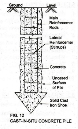
A
bore is dug into the ground by inserting a Casing. The reinforcement made of
Main Reinforcement Rods and Lateral Reinforcement Rods (called Stirrups) are
placed into the ground. The bore is filled with cement concrete.
In
the case of Simplex Pile, the casing is withdrawn from the bore after placing
the concrete as shown in Fig. 12. Hence, it is called Uncased Cast-in-situ
Concrete Pile.
Raymond
Pile: In this, the casing is kept in position inside the
ground. Concrete is then poured. Casing is not withdrawn. Hence, it is called
Cased Cast-in-situ Pile.
Pre-cast
Concrete Piles
These
piles are cast in a yard and transported to the site. Concrete pile is pre-cast
to specified lengths and shapes with reinforcement. The reinforcement enables
the pile to resist the bending moment developed during lifting and transportation.
Pre-cast
piles may be square, circular or octagonal in section. Fig. 13 shows a Pre-cast
Square Pile with corners chamfered.
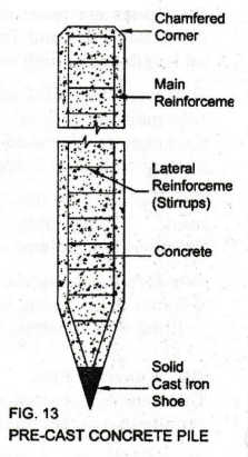
A
Solid Cast Iron Shoe is provided to prevent the lower end from breaking, if it
strikes a boulder underground. The pile shoe should be coaxial with the pile.
It is firmly fixed to the concrete.
The
depth to which the pile has to be driven is determined by preliminary borings.
This will prevent over-driving of piles.
(iii)
Timber Pile
Timber
Pile is the oldest type of pile made from tree trunks. The length of a timber
pile should not exceed 20 times it top width to avoid buckling. The life of
timber piles may increased by treating them with preservatives. At the bottom
of the pile, an iron shoe is provided. At the top, a steel plate is fixed.
(iv)
Composite Pile
It
is made up of two different materials driven one above the other. Steel and
concrete combination or timber and concrete combination of composite piles are
in use. Timber pile or steel pile is provided below the ground water level.
Concrete pile is provided above the timber or steel piles.
2.
Classification Based on Installation Methods
Based
on installation techniques, piles are classified as Cast-in-situ piles and
Driven piles. Cast-in-situ Piles: These piles are explained above in detail.
Driven Piles: Driven piles may be made of Concrete, Steel or Timber. These are
explained above in detail.
3.
Classification Based on Functions or Uses
(i)
End-bearing Piles: See Fig. 14. If the top soil is very weak, piles are used to
transmit the load of the superstructure directly to the underlying bed rock or
hard stratum. Such piles are called End-bearing Piles. Endbearing piles are
resting on a very hard stratum.
The
soil through which these piles have passed are not assumed to resist the loads.
The soil provides only lateral support to the piles.
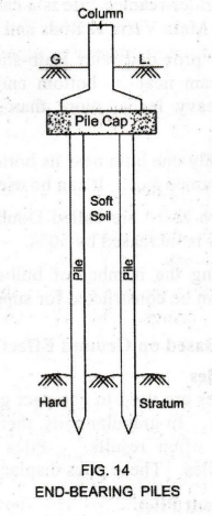
Two
or more piles support one Column. These piles form one group, provided with a
common concrete top, called Pile Cap. Column of the structure is resting on the
Pile Cape cap. The pile cap distributes
the load equally to the piles.
End-bearings
piles may be Concrete Piles, Steel Sheet Piles and Timber Piles.
(ii)
Friction Piles: See Fig. 15. If the bed rock does not
exist at a reasonable depth below the Ground Level, the load is transferred by
friction along the pile length. Such piles are called Friction Piles.
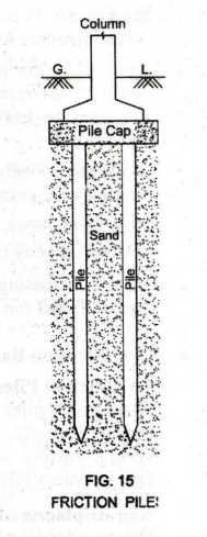
In
these piles, Skin Friction (frictional Stratum resistance) is developed between
the surface of the piles and the sand particles surrounding them. Skin Friction
transfers the load along the length of the piles.
Since
friction piles do not rest on hard stratum, they are also known as Floating
Piles.
Uses
•
Friction piles are used where deep bed of sand is available.
•
The frictional resistance of the surrounding soil against the downward movement
of the pile can be increased by providing a longer pile, a greater diameter for
the pile, a rough lateral surface to the pile and by providing piles in group.
Friction
piles may be Cement Concrete Piles, Steel Piles and Composite Material Piles.
(iii)
Under-reamed Piles
In
Expansive Soils such as black cotton soil, very soft clay, filled-up earth,
etc., building cracks due to relative ground movements. This differential
settlement is caused by alternate swelling and shrinking of the soil due to
changes in its moisture content.
To
avoid differential settlements, the structure is anchored to a depth where the
volumetric change of soil due to Lateral seasonal variations is negligible.
This can be Stirrup economically obtained in shallow as well as deep layers of
expansive soil by using Under-reamed Pile.
Load
is transferred to hard strata of high bearing capacity. In fact, the building
structure is anchored to the ground by Under-Reams using under-reamed piles.
See
Fig. 16. Under-reamed Pile is a cast-in-situ pile. It is reinforced by Main
Vertical Rods and Lateral Stirrups.

These
piles are provided with Bulb-shaped Enlargement Under-ream near its bottom end.
If the pile is subjected to heavy loads, more than one bulb can be provided.
A
pile having only one bulb near its bottom is known as Single Under-reamed Pile.
It can be used successfully for one and two storey buildings.
Piles
having two bulbs are called Double Under-reamed Piles. With one additional
bulb, bearing capacity is increased by 50%.
So,
by increasing the number of bulbs, very high capacity piles (called Multiple
Underreamed Piles) can be constructed for supporting multi-storey buildings and
heavy structures.
4.
Classification Based on Ground Effects
Compaction
Piles
Compaction
piles are used to compact granular soil, thus increasing their density and in
turn bearing capacity. In granular soils, there is a tendency for compaction.
In clays, heaving of ground surface often results. Piles used to compact soils
are called Compaction or Displacement Piles. These piles displace substantial
volume of soil during installation.
Non-displacement
Piles
Driven
piles installed in pre-drilled holes are called Non-displacement Piles. These
piles are used to prevent the movement of earth slopes and to safeguard the
foundation from damage due to scour.
3. PIER FOUNDATIONS
Piers
are Large Diameter Massive Shafts with or without Broad Base at the bottom.
Deep holes are drilled into the ground. Piers are installed by placing R.C.C.
concrete-in-situ. Hence, piers are also known as Drilled Piers.
Broad
Based Pier or Belled Pier: See Fig. 17.

Drilled
piers are provided with a Broad Base at the bottom of the straight shaft. These
are known as Broad Based Pier or Belled Pier. The bell is angled as shown.
Advantage:
Vibration is not caused as in the driven pile installation.
Uses:
Equipments used in the construction of drilled piers produce less noise.
Therefore, piers are quite suitable for areas near hospitals and educational
institutions. Drilled piers are used in the area where it is difficult to
install pile foundation.
4. WELL FOUNDATION
See
Fig. 18. Well foundation is hollow inside, resembling a well. It has no top or
bottom cover.

A
Well Curb of steel or R.C.C. is constructed in a yard. It is placed where the
well has to be sunk.
The
soil from inside the curb is dug. The Cutting Edge is sharp for knifing into
the soil. The well is gradually driven down till the required depth of reaching
a hard stratum. The soil inside the well is removed and the well is made to
sink.
After
installing the curb in place, a Masonry Well Steining is constructed above it.
Then,
the bottom of the well is plugged with concrete. It is known as Bottom Plug. It
is bowlshaped so as to have inverted arch action. The hollow portion above the
bottom plug is filled with sand. It is called as Top Plug. Well is covered with
Well Cap.
Shapes
of wells in foundation are: Circular, Rectangular, Twin circular, Double-D,
etc. See Fig. 19.

Advantages
and Uses
•
Well foundation is provided in soils which are sandy and soft for great depths.
This foundation is meant for heavily loaded structures on low bearing capacity
soils.
•
Well foundations are used under-water such as bridges, docks, etc.
Bridges/docks have to resist large lateral forces and are located in shallow
running water in rivers with heavy scour. It is believed that the famous Taj
Mahal is built on brick wells.
Basic Civil & Mechanical Engineering: UNIT III: a. Foundations or substructures : Tag: : Uses, Types, Advantages, Classification - Deep foundations
Related Topics
Related Subjects

Basic Civil and Mechanical Engineering
BE3255 2nd Semester 2021 Regulation | 2nd Semester EEE Dept 2021 Regulation