Electrical Machines: Unit II: D.C. Generators
Demagnetising and Cross Magnetising Conductors
DC Generators
Thus these conductors are in direct opposition to main field and called demagnetising armature conductors.
Demagnetising
and Cross Magnetising Conductors
AU: Dec.-06, 19, May-07, 17
•
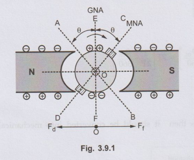
The conductors which are responsible for producing demagnetising and distorting
effects are shown in the Fig. 3.9.1.
•
The brushes are lying along the new position or MNA which is at angle from GNA.
The conductors in the region AOC = BOD = 2 θ at the top and bottom of the
armature are carrying current in such a direction as to send the flux in
armature from right to left. Thus these conductors are in direct opposition to
main field and called demagnetising armature conductors.
•
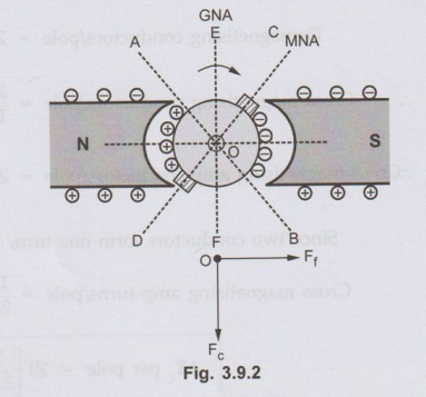
The remaining armature conductors which are lying in the region AOD and BOC
carry current in such a direction as to send the flux pointing vertically
downwards i.e. at right angles to the main field flux. Hence these conductors
are called cross magnetising armature conductors which will cause distortion in
main field flux.
•
These conductors are shown in the Fig. 3.9.2.
1. Calculation of Demagnetising and Cross Magnetising Amp-Turns
•
Let us find the number of demagnetising and cross magnetising amp-turns.
Let
Z = Total number of armature conductors
P
= Number of poles
I
= Armature conductor current in Amperes
=
1a/2 for simplex wave winding = Ia/P for simplex lap
winding
θm
= Forward lead of brush in mechanical degrees.
•
The conductors which are responsible for demagnetising ampere-turns are lying in
the region spanning 4 θm degrees. The region is between angles AOC and BOD, as shown in the Fig.
3.9.2.
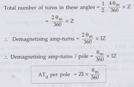
Total
number of armature conductors lying in angles AOC and BOD = 4 θm/360
× Z
Since
two conductors form one turn,
Total
number of turns in these angles =
•
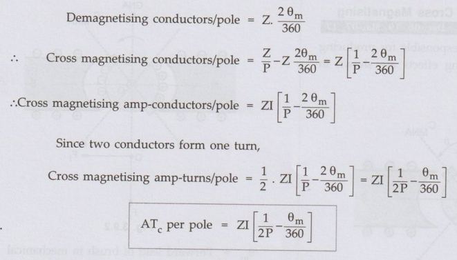
The conductors which are responsible for cross magnetising ampere-turns are
lying between the angles AOD and BOC, as shown in the Fig. 3.9.2.
Total
armature-conductors/pole = Z / P
•
From above we have found an expression for demagnetising conductors per pole.
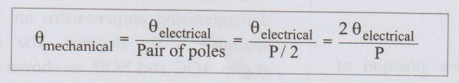
• If the brush shift angle is given in electrical degrees then it should be
converted into mechanical degrees by using the relation,
•
For neutralizing the demagnetizing effect of armature reaction, an extra number
of winding turns are provided on each pole. To calculate its number,
Number
of extra turns/pole A Tdλ / I
Where
λ = Leakage coefficient
I
= Ish for shunt generator
I
= Ia for series generator
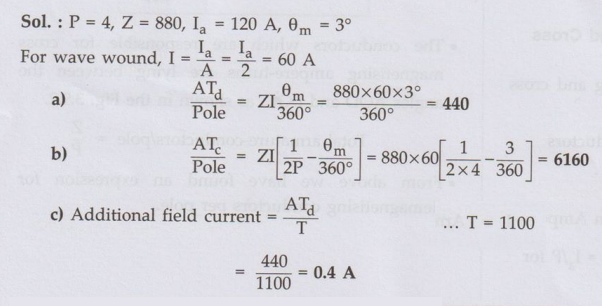
Ex. 3.9.1
A 4 pole wave wound DC motor armature has
880 conductors and delivers 120 A. The brushes have been displaced through 3
angular degrees from the geometrical axis. Calculate.
a) The demagnetizing
ampere-turns/pole,
b) The cross magnetizing ampere
turns/pole
c) The additional field current for
neutralizing the demagnetization of the field winding has 1100 turns/pole. AU:
Dec.-19, Marks 8
Sol :
Ex 3.9.2 The brushes of a 400 kW, 500 V,
6-pole D.C. generator is given a lead of 12° electrical. Calculate i) The
demagnetizing ampere-turns, ii) The cross-magnetizing ampere-turns and iii)
Series turns required to balance the demagnetizing component. The machine has
1000 conductors and the leakage coefficient is 1.4. AU:
May-07, Marks 8
Sol.

iii)
Series field winding is in series with armature carrying full load armature
current of 800 A. Series turns required to balance demagnetizing component,

Review Questions
1. How demagnetizing
and cross magnetizing ampere-turns are calculated?
AU: Dec.-06, May-17,
Marks 4
2. A wave wound 4
pole d.c. generator with 480 armature conductors supplies a current of 144 A.
The brushes are given an actual lead of 10°. Calculate the demagnetising and
cross magnetising amp turns per pole. (Ans.: 960, 3360)
3. The brushes of a lap connected 400 kW, 6
pole generator are given a lead of 21 degrees electrical. From the data given,
calculate i) The demagnetising AT ii) The cross magnetising AT and iii) Series
turns required to balance the demagnetising component.
The full load current
is 750 A and total number of conductors are 900 and the leakage coefficient is
1.4 (Ans. i) 2187.5, ii) 7187.5, iii) 4)
Electrical Machines: Unit II: D.C. Generators : Tag: : DC Generators - Demagnetising and Cross Magnetising Conductors
Related Topics
Related Subjects

Electrical Machines I
EE3303 EM 1 3rd Semester EEE Dept | 2021 Regulation | 3rd Semester EEE Dept 2021 Regulation