Transmission and Distribution: Unit II: (a) Modelling and Performance of Transmission Lines
Determination of Capacity for Synchronous Phase Modifier
Modelling and Performance of Transmission Lines
We already know that synchronous machine can take lagging or leading current depending upon whether it is under excited or overexcited.
Determination of Capacity
for Synchronous Phase Modifier
We already know that synchronous machine
can take lagging or leading current depending upon whether it is under excited
or overexcited.
If idle running synchronous machine is
used for voltage regulation by connecting it in parallel with the load at
receiving end of the line then it may take lagging or leading current. When it
is used in this manner, it is referred as phase modifier.
Phase modifiers are not designed for
driving any mechanical load and are built for highest possible economic speeds.
These are equipped with smaller shafts and bearings and high overall
efficiency. Its capacity can be calculated as follows. Consider the following
phasor diagram shown in Fig. 2.16.1.

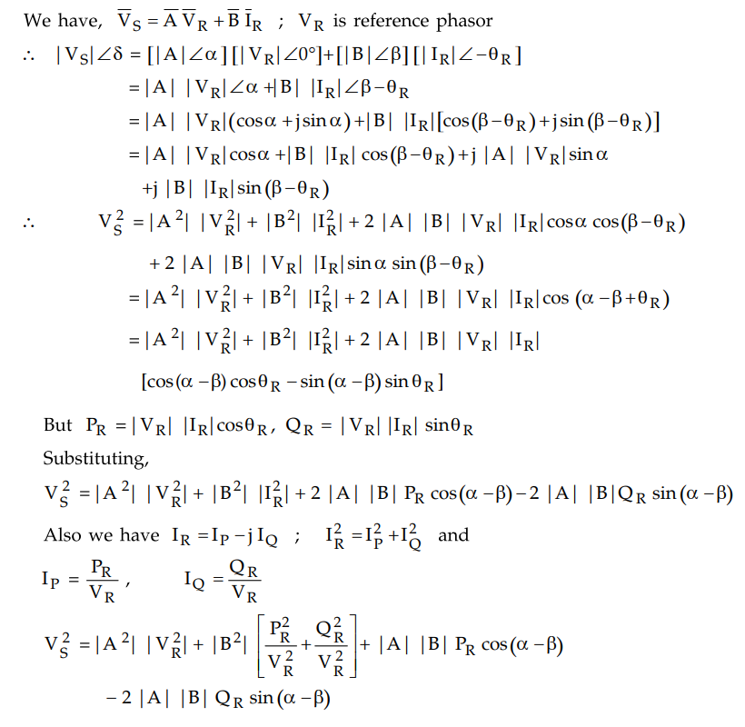
When all the quantities such as A, B, PR
, α, β and VR are known, VS can be obtained. The above
expression can be used for this purpose.
Sometimes voltages at sending end and
receiving end are kept constant and
A, B, PR, α, β and QR
(load) are given and it is required to find out capacity of phase modifier. In
this case the required quantity is QR. This net QR can be
obtained from above equation. From that capacity of phase modifier can be
determined.
Example 2.16.1
A 3 phase line has an impedance per phase of (5 + j 20) Ω/phase. The load at
the receiving end is 30 MW at 33 kV, 0.8 p.f. lag. Find the sending end
voltage. If a synchronous phase modifier is inserted at the receiving end and
the voltage at both the ends are maintained at 33 kV. Find the kVAR rating of
the modifier for the above load conditions. Also find the maximum load that can
be transmitted.
Solution :

If synchronous phase modifier is used so
that VR = VS =33 kV.
The equation for VS remains same only we
will now find QR

This is net VAR requirement which is
obtained.
QRnet = -20.29 MVAR
We have the equation,
QRnet + QC = QL
where QC is the VAR supplied
by phase modifier
QC = QL - QRnet
= (22.5)-(- 20.29)
QC = 42.8 MVAR
This must be rating of phase modifier.
Maximum power transmitted is given by,

Example 2.16.2
A 3 phase overhead line has resistance and the reactance per phase of 5 Ω
and 25 Ω respectively. The load at the receiving end is 15 MW, 33 kV, 0.8 p.f.
lagging. Determine the capacity of the compensation equivalent needed to
deliver this load with a sending end voltage of 33 kV.
Solution :

We have, QRnet + QC
= QL
where QC is the VAR supplied
by the phase modifier
QC = QL -QRnet
= (11.25)-(-6.1327) = 17.38 MVAR
This is the rating of the phase
modifier.
Review Question
1. Explain how capacity of synchronous phase modifier can
be determined.
Transmission and Distribution: Unit II: (a) Modelling and Performance of Transmission Lines : Tag: : Modelling and Performance of Transmission Lines - Determination of Capacity for Synchronous Phase Modifier
Related Topics
Related Subjects

Transmission and Distribution
EE3401 TD 4th Semester EEE Dept | 2021 Regulation | 4th Semester EEE Dept 2021 Regulation