Electron Devices and Circuits: Unit II: (d) UJT Thyristor and IGBT
Diac
Construction, Principle of Operation, Symbols, Equivalent Circuit, Characteristics, Applications
• The diac is a two terminal, four layer device. It conducts in either directions hence it is also called bilateral trigger diode.
Diac
•
The diac is a two terminal, four layer device. It conducts in either directions
hence it is also called bilateral trigger diode.
•
It has a pair of four layer diodes a shown in the Fig. 5.4.1 (a). The two
different symbols used for the diac are shown in the Fig. 5.4.1(b).

•
The terminals of the diac are not named as it can be used in any direction. It
is low power triggering device.
•
There is no control terminal on the diac.
1. Basic Operation
•
The diac can be treated as parallel inverse combination of the semiconductor
layers that permits triggering in either direction.
•
The Fig. 5.4.2 (a) shows the diac equivalent circuit as two parallel Shockley
diodes, connected in opposite directions. The Shockley diode is basically a
four layer pnpn diode, with only two external terminals. The characteristics of
Shockley diode are similar to SCR with IQ =0. It acts as a switch which is ON
in one direction and OFF in the other.
•
Both the Shockley diodes act as a switch as shown in the Fig. 5.4.2 0?). The V
is the applied voltage across A-j and A2.
•
When the polarity of applied voltage is as shown in the Fig. 5.4.2 (a) then
Shockley diode DS1 becomes ON when V is more than VBRof DS1. Thus current flows
from A1 to A2 as DS1 acts as closed switch S1.

• If the polarities of applied voltage V are
reversed then for applied voltage more than VBRof DS2, the DS2 conducts and its
acts like a closed switch S2. The current flows from A2 to A1.
•
Thus device can conduct in both the directions, depending on the polarities of
the applied voltage across it.
2. Four Transistors Analogy
•
The diac operation can be explained using four transistors analogy.
•
Each pair of transistors form a Shockley diode. The four transistors analogy
and the biasing conditions shown in the Fig. 5.4.3 (a) and 0?) also can be used
to explain the basic operation of diac.
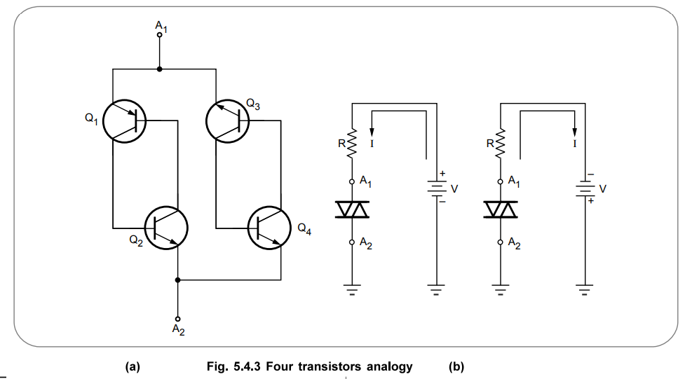
•
The transistors Q1,Q2 form a Shockley diode DS1
while the transistors Q3, Q4 form a Shockley diode DS2.
The basic operation remains same as explained earlier.
3. Characteristics of Diac
•
The diac characteristics are shown in the Fig. 5.4.4.
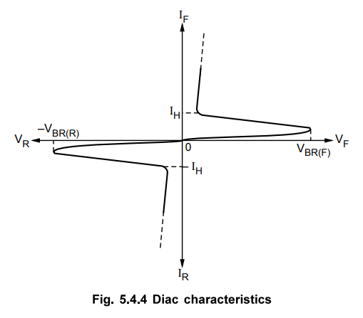
•
As long as the forward voltage is less than the breakdown voltage, the diac is
OFF and the current is small.
•
When the applied forward voltage becomes more than VBR(F) then diac
becomes ON and conducts so that large current flows through it.
•
The diac remains ON as long as the current through it is greater than the
holding current.
•
The diac characteristics are exactly similar in both the directions. But they
are shown in the 1st quadrant and in the 3 rd quadrant due to opposite
polarities of voltage and current in the two directions.
4. Applications
•
The diac is not a control device, it is used as a triggering device.
•
It is used in,
1.
Triggering of triac
2.
Motor speed control
3.
Temperature control
4.
Light dimming circuits.
Review Questions
1. Explain the basic construction of a diac.
2. Explain the working principle of diac.
3. Explain the four transistor analogy for a diac.
4. Draw and explain the characteristics of diac.
5. List the applications of diac.
Electron Devices and Circuits: Unit II: (d) UJT Thyristor and IGBT : Tag: : Construction, Principle of Operation, Symbols, Equivalent Circuit, Characteristics, Applications - Diac
Related Topics
Related Subjects

Electron Devices and Circuits
EC3301 3rd Semester EEE Dept | 2021 Regulation | 3rd Semester EEE Dept 2021 Regulation