Electric Circuit Analysis: Chapter - 1: Basic Circuit Analysis - DC
Difference between series and parallel circuits
with Example Problems
Difference between series and parallel circuits
DIFFERENCE BETWEEN SERIES AND PARALLEL CIRCUITS

EXAMPLE
9:
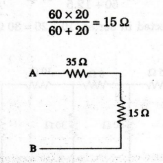
Figure shows 3 resistors RA, RB and Rc connected in series to a 250 V
source. Given Re = 50 Q, and VB = 80 Volts when the
current is 2 amperes, calculate the resistances RA and RB.

Solution
Current
flowing through the circuit, I = 2 A
Voltage
across resistor RB, VB = 80 V
VB
= IRB

RA
= 35 Ω
EXAMPLE
10:
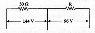
A resistor of ohmic value 30 22 is connected in series with an unknown
resistor. The potential drop across the two resistors are 144 V and 96 V
respectively. Find the value of the unknown resistor.
Solution
Let
the current flowing through the two resistors be I
Then,
voltage across the 30 Ω resistor = 30 I = 144 V
Therefore,
I = 144 / 30 = 4.8 A
Let
the unknown resistor be R ohms. The voltage drop across R is
IR
= 96 V
Therefore,
R = 96 / I = 96 / 4.8 = 20 Ω
R
= 20 Ω
EXAMPLE
11:
Two resistors connected in parallel across 200 V supply take 10 A from the
mains. If the power dissipated in one resistor is 800 W, find the value of the
other resistor.
Solution
Total
power taken P = V × I = 200 × 10 = 2000 W
Power
dissipated in one resistor P1 = 800 W
Therefore,
power dissipated in the other resistor

R
= 32.33 Ω
EXAMPLE
12:
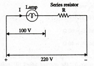
A lamp rated 500 W, 100 V is to be operated from 220 V supply. Find the
value of the resistor to be connected in the series with the lamp. How much
power is lost in the resistor?
Solution
Current
in the lamp = P/V = 500 / 100 = 5 A
Since
voltage drop across the lamp is 100 V, voltage to be dropped in the series resistor
220-100 120 V.
Therefore,
value of the resistor R = 120 / 5 = 24Ω
Power
lost in the resistor I2 × R = 52 × 24 = 600 W.
EXAMPLE
13:
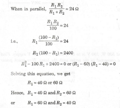
The effective resistance of two resistors connected in series is 100 9. When
connected in parallel, the effective value is 24 2. Determine the values of the
two resistors.
Solution
Let
the two resistors be R1 and R2
When
in series, R1 + R2 = 100 Ω
R2
= 100 – R1
EXAMPLE
14:
A 60 W, 240 V lamp is connected in series with a 40 W, 200 V lamp across
250V supply. Calculate (i) the current taken (ii) voltage across each lamp and
(iii) power given by the lamps. Assume that the resistance of the lamps remains
constant.
Solution
Resistance
of 60 W lamp = V2 / P = (240)2 / 60 = 960 Ω
Resistance
of 40 W lamp = V2 / P = (200)2 / 40 = 1000 Ω
When
both lamps are in series, total resistance is the sum of the resistances of each
lamp.
i.e;
Rtotal = 960 + 1000 = 1960 Ω
(i)
Current = V / Rtotal = 250 / 1960
= 0.12755 A
(ii)
Voltage across 60 W lamp = 0.12755 × 960 = 122.45 V
Voltage
across 40 W lamp = 0.12755 × 1000 = 127.55 V
(iii)
Power (Lamp 1) = 0.12755 × 122.45 = 15.62 W
Power
(Lamp 2) = 0.12755 × 127.55 = 16.27 W
EXAMPLE
15:
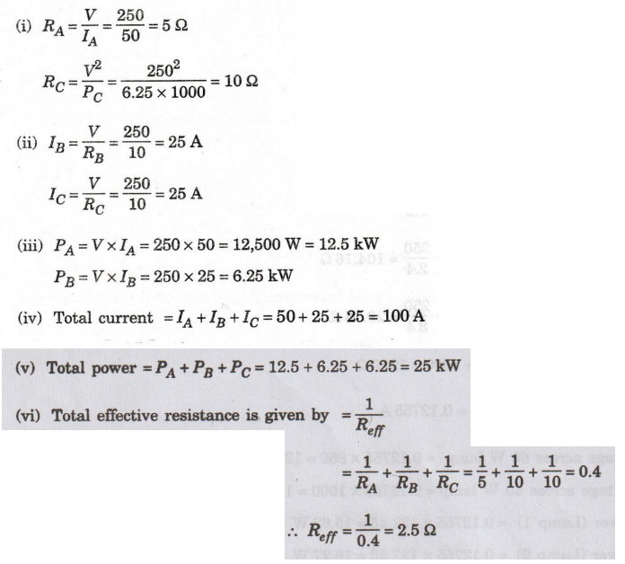
Three loads A, B and C are connected in parallel across a 250 V source. Load A
takes 50 A. Load B is a resistor of 10 2 and load C takes 6.25 kW. Calculate
(i) RA and Rc (ii) the currents Ig and Ic (iii) power in loads A and B (iv)
total current (v) total power and (vi) total effective resistance.

Solution
EXAMPLE
16:
Three resistors A, B and C connected in parallel take a total current of 12
A from the supply. IB = 21A and Ic=3.5 IB. If the total power taken is 3 kW,
calculate (i) the current taken by the loads (ii) the individual resistance
values (iii) the supply voltage and (iv) the individual powers.
Solution

EXAMPLE
17: Two 60 2 resistors are connected in
series. If a resistor R is connected across one of them, the total circuit
resistance becomes 80 2. Find the value of R.
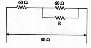
Solution
Total
circuit resistance = 80 Ω
i.e.,
80 = 60+ 60 Ω parallel with R or 80= 60 +
60 R / 60 + R
Therefore,
60 R / 60 + R = 80 - 60 = 20
R
= 30 Ω
EXAMPLE
18:
Determine the effective resistance between terminals A and B in the circuit
of figure (a). If the current drawn at A is 9 A, find the current and the
voltage drop across each element.
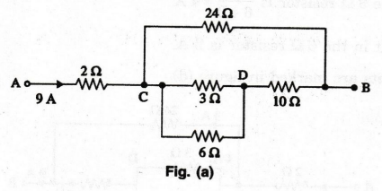
Solution
The
parallel combination of 32 and 6 2 between C and D gives
=
3 × 6 / 3 + 6 = 2Ω
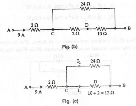
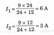
The
circuit can be simplified as in figures (b) and (c). The current approaching
the point C splits into two parts one along the 12 Ω resistor and the other
along the 24 Ω resistor, both being in parallel. The currents I1 and
I2 can be found out from current division rule.
Referring
to figure (a) the 6 A leaving point C splits like wise into 2 parts and the
current through the 3 Ω resistor is 6 × 6 / 6 + 3 = 4 A
The
current in the 6 Ω resistor is 2 A.
All
the currents are marked in figure (d).
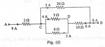
Voltage
drop across 2 Ω resistor = 9 × 2 = 18 V
Voltage
drop across 3 Ω resistor = 4 × 2 = 12 V
Voltage
drop across 6 Ω resistor = 6 × 10 = 60 V
Voltage
drop across 10 Ω resistor = 6 × 10 = 60 V
Voltage
drop across 24 Ω resistor = 3 × 24 = 72 V
EXAMPLE
19:
A 10 Ω resistor is connected in series with two 15 2 resistors connected is
parallel. What resistance must be shunted across this parallel combination so
that the total current taken from 20V supply is 1.5 A.
Solution
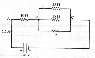
Let
R be the resistance to be shunted across the parallel combination.
Voltage
drop across AB = 1.5 × 10 = 15 V
Therefore,
voltage drop across BC = 20 - 15 = 5 V
Current
in each 15 Ω resistor = 5/15 = 1/3 A
1/3
A flows through each of 15 Ω resistor. The remaining current (i.e. 1.5 2 × 1/3)
flows through R.
Current
through R = 1.5-2/3=0.833 A
Voltage
across R = 5 Volts
R
= V / I = 5 / 0.8333 Ω
Therefore,
R
= 6 Ω
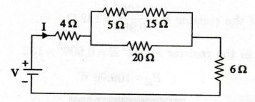
EXAMPLE
20:
If 20V is applied across AB, in the circuit of figure (a), calculate the
total current, the power dissipated in each resistor and the value of the
series resistance to halve the total current.

Solution
The
circuit can be reduced in steps to the form given in figure (b).
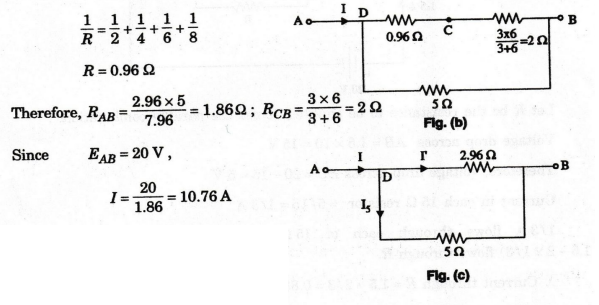
At
D, this current splits, such that the current through the 5 Ω resistor is
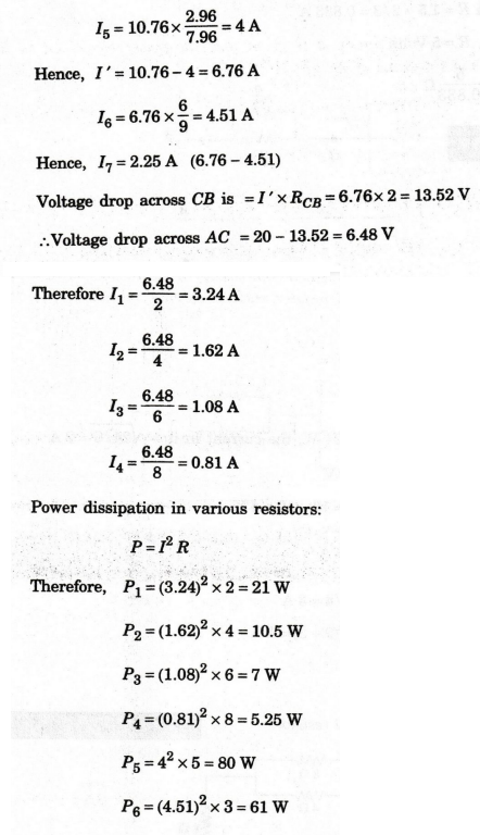
If
the total current were to be halved, the resistance RAB has to be doubled.
Hence, the extra resistance to be added is the same as RAB (i.e.,
1.86 Ω ).
EXAMPLE
21:
In the circuit of figure, it is given that the power consumed in the 6 Ω
resistor is 24 W. Find the value of R.
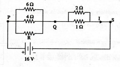
Solution
P
= I2 R
I
= √P/R
Since
power in the 6 2 resistor is 24 W, the current in it = √24/6 = 2 A
Voltage
drop across PQ = 2 × 6 = 12 V
Therefore,
voltage drop across QS = 16 - 12 = 4 V
Current
I = VQS / RQS = ( 4 / (2×1) / (2 + 1) ) = 6 A
Current
through 4 Ω resistor = 12/4 = 3A
Therefore,
current through R = 6 - (2 + 3) = 1A
R
= VPQ / I = 12 / I = 12 Ω
EXAMPLE
22:
Find the current in 4 Ω resistor.
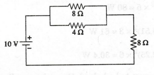
Solution
Here,
8 Ω and 4 Ω are connected in parallel.
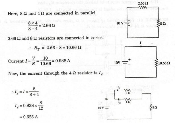
The
current through 4 Ω resistor is 0.625A
EXAMPLE
23:
Two resistors 4 Ω and 6 Ω are connected in parallel. If the total current is
12 A, find the current through each resistor.
Solution:
By
using current division rule

I1
= 7.2 A
I2
= 4.8 A
EXAMPLE
24:
Two coils connected in series have a resistance of 182 and when connected in
parallel of 4 2. Find the value of resistance of the two coils. (AU/ECE -
May 2005)
Solution:
Let
R1, R2 be the resistance of the coils.
Given
R1 + R2 = 18 Ω &
R1
R2 / R1 + R2
= 4Ω
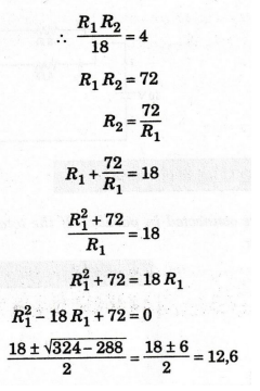
R1
= 12 Ω , R2 = 6 Ω
EXAMPLE
25:
The element of 500 W electric iron is designed for use on a 200 V supply.
What value of resistance is needed to be connected in series in order that iron
can be operated from 240 V supply.
Solution
Resistance
of electric iron R = V2 / P = 2002 / 500 = 80 Ω
Now,
this electric iron is to be operated from 240V and a resistance is connected in
series with electric iron.
From
this circuit,
I
= P / V = 500 / 200 = 2.5 A
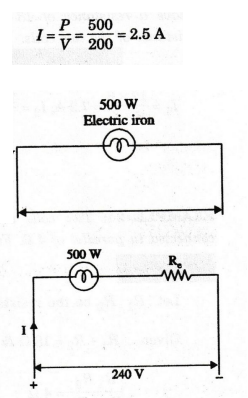
Since
voltage drop across the lamp is 200 V, voltage to be dropped in the series
resistor = 240 - 200 = 40 V
The
value of the resistor Re = 40 / 2.5 = 16 Ω
Re
= 16 Ω
EXAMPLE
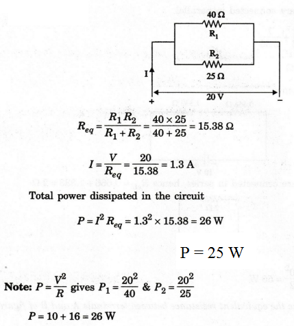
26:
Two resistors R1 = 40 Ω and R2 = 25 Ω
are connected in parallel across 20 V DC supply. Find the total power
dissipated in the circuit.
Solution
EXAMPLE
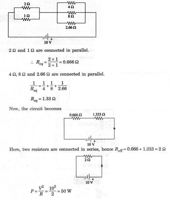
27:
Calculate the total power supplied by the battery in the network shown in
figure.
Solutuion
EXAMPLE
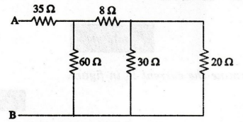
28:
Determine the equivalent resistance between terminals A and B of figure
shown below.
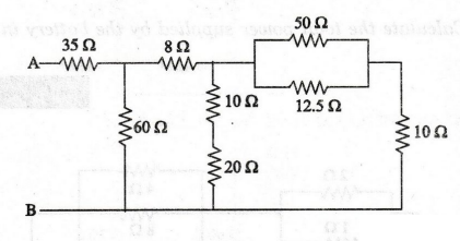
Solution
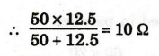
50
Ω and 12. 5 Ω are connected in parallel.
10
Ω and 20 are connected in series, 10 + 20 = 30 Ω
Now,
circuit becomes

10
Ω and 10 Ω are connected in series 10 + 10 = 20 Ω
30
and 20 Ω are connected in parallel.
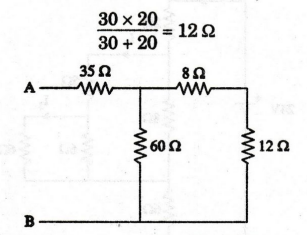
8
Ω and 12 Ω are connected in series 8+12=20 Ω
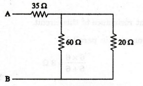
60
Ω and 20 Ω are connected in parallel.
35
Ω and 15 Ω are connected in series.
RAB
= 35 + 15 = 50 Ω
RAB
= 50 Ω
EXAMPLE
29:
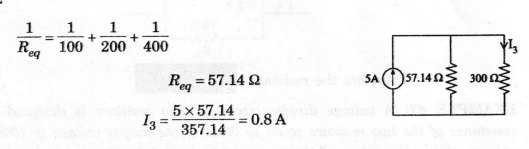
Determine the current I3 in figure.

Solution
First
find equivalent resistance of this circuit.
6
Ω and 6 Ω are connected in parallel.
6
× 6 / 6 + 6 = 3 Ω

EXAMPLE
30:
What is the potential across 5 Ω resistor in the circuit?

Solution
Here,
three resistors are connected in series,
Req
= 3+5+2=10 Ω
I
= V / Req = 10 / 10 = 1 A
Voltage
across 5 Ω = IR = 1 × 5 = 5 V
EXAMPLE
31:
For the circuit shown in figure, calculate equivalent resistance of the
circuit and the total circuit current.

Solution
4
Ω, 5 Ω and 6 Ω are connected in series.

EXAMPLE
32:
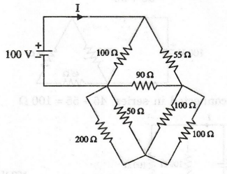
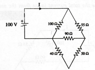
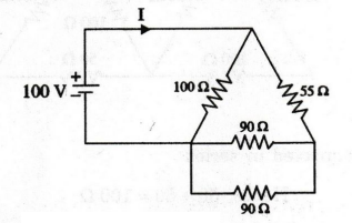
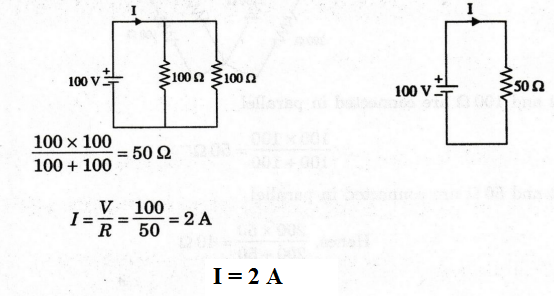
Determine the total current taken from the source. (MKU/I YEAR - Apr
2002)

Solution
50
Ω and 50 Ω are connected in series
Hence,
50 + 50 = 100
100
Ω and 100 Ω are connected in series
So,
100 + 100 = 200 Ω
100
Ω and 100 Ω are connected in parallel
(100
× 100 / 100 + 100) = 50 Ω
200
Ω and 50 Ω are connected in parallel
Hence,
(200 × 50 / 200 + 50) = 40 Ω
40
Ω and 50 Ω are connected in series, 40 + 50 = 90 Ω
90
Ω and 90 Ω are connected in parallel.
90
× 90 / 90 + 90 = 45 Ω
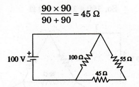
45
Ω and 55 Ω are connected in series, 45 + 55= 100 Ω
EXAMPLE
33:
For the circuit shown in figure, the power consumed by 62 resistor is 150 W.
Find the supply voltage.
Solution
Power
consumed by 6 Ω resistor 150 W
Current
flow through 6 Ω resistor I = √P/R = √150/6 = 5A
Current
supplied by the battery is also 5 A.
Input
voltage V = I Req

EXAMPLE
34:
A filament lamp is rated for 100 W, 110 V. Find the value of the resistance
to be connected in series with this lamp so that it can be operated on a 230 V
supply. What is the power loss in the resistor?
Solution

Current
in the lamp I = P / V = 100 / 110 = 0.909 A
Since
voltage drop across the lamp is 110 V, voltage to be dropped in the series
resistor = 230 - 110 = 120 V
Therefore
value of the resistor R = 120 / 0.909 = 132 Ω
Power
dissipated in the resistor PR = I2 R = 0.9092
× 132
PR
= 109.06 W
PR
= 109.08 W
EXAMPLE
35:
When a resistor is placed across a 230 V supply, the current is 12 A. What
is the value of the resistor that must be placed in parallel to increase the
load current to 16 A.
Solution

EXAMPLE
36:
Find (i) Current in 15 Ω resistor, (ii) Voltage across 18 Ω
resistor, (iii) Power dissipated in 7 Ω resistor in the circuit shown
below.
(AW/Mech
- Dec 2005)
Solution:

(i) Current through 15 Ω resistor
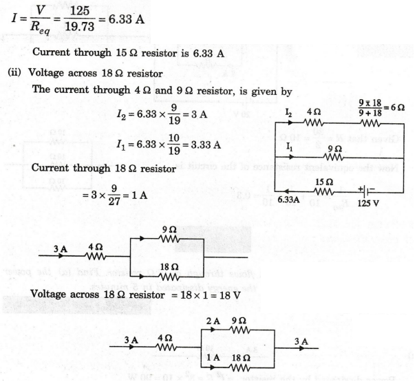
(iii)
Power dissipated in the 7 Ω resistor
Current
through 2 Ω and 7 Ω resistor is 3.33 A
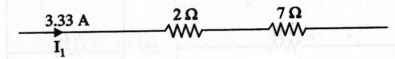
Therefore,
power dissipated in the 72 resistor = 3.332 ×7 = 77.62 W
EXAMPLE
37:
Three resistors of equal resistances are connected in parallel across a 20 V
de source. If the current through one of the resistors is 2 A, what is the
value of equivalent resistance of the parallel connected resistors.
Solution

Req
= 3.33 Ω
EXAMPLE
38:
A current of 3A flows through a 10 2 resistor. Find (a) the power dissipated
by the resistor and (b) the energy dissipated in 5 minutes.
Solution

Power
dissipated by the resistor =I2 R = 32 × 10 = 90 W
(b)
Energy dissipated in 5 minutes
5
minutes = 5 × 60 = 300 second
Energy
= Power × time = 90 × 300 = 27000 W- second
EXAMPLE
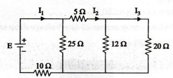
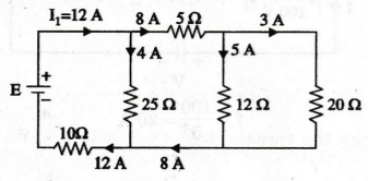
39:
Find the supply voltage E such that the power in the 20 resistor is 180 W.
Solution
Power
in the 20 Ω resistor = 180 W
Current
through 20 Ω resistor (I3) is given by
I23
R=180
I3
= √180 / 20 = 3A
Voltage
across 20 Ω resistor = I3 R = 3 × 20 = 60 V
This
60 V is applied across 12Ω resistor.
Therefore,
the current flow through 12 Ω resistor = 60 / 12 = 5A
I2
= 5 + 3 = 8 A
Voltage
drop across 5 Ω resistor = 5 × 8 = 40 V
Voltage
drop across 25 Ω resistor
=
Voltage drop across 5Ω + Voltage drop across 12 Ω
=
40 + 60 = 100 V
Current
through 25 Ω resistor = 100 / 25 = 4A
I1
= 4 + 8 = 12A
Current
through 10 Ω resistor = 12 A
Voltage
across 10 Ω = 12 × 10 = 120 V
Input
voltage E = Voltage drop across 25 Ω + Voltage drop across 10 Ω
=
100 + 120 = 220 V
E
= 220 V
EXAMPLE
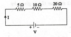
40:
For the circuit shown in figure, (1) find the equivalent resistance across
the supply. (2) if the voltage drop across 5 Ω is 100 V, find the supply
voltage (3) find the power consumed by each resistor.
Solution
1.
Equivalent resistance of the circuit is
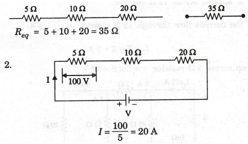
Voltage
drop across 10 Ω = 20 × 10 = 200 V
Voltage
drop across 20 Ω = 20 × 20 = 400 V
Supply
voltage = 100 + 200 + 400 = 700 V
V
= 700 V
3.
Power consumed by 5 Ω resistor = I2 R = 202 × 5 = 2000 W
Power
consumed by 10 Ω resistor = 202 × 10 = 4000 W
Power
consumed by 20 Ω resistor = 202 × 20 = 8000 W
EXAMPLE
41:
Find the voltage between A and B in a voltage divider network shown in
figure.
Solution:
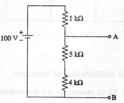
Equivalent
resistance Req = 1 k Ω + 5k Ω + 4k Ω = 10 k Ω
Current
in the circuit I = V / Req = 100 / 10 k Ω = 0.01 A
Voltage
drop across AB = 0.01 × 9kΩ = 90 V
EXAMPLE
42:
Find the current through 10 2 resistor for the following circuit.
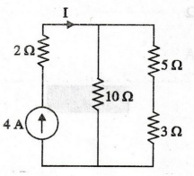
Solution
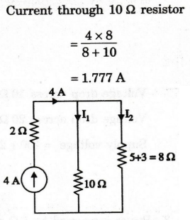
I10
Ω
= 1.777A
EXAMPLE
43:
Find the current supplied by the 60 V source in the network.
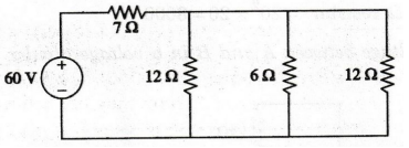
Solution
First
reduce the parallel combination of resistors.

EXAMPLE
44:
If Req = 50 Ω in the circuit shown in figure, find the value of
R.
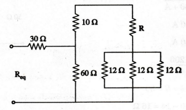
Solution
Three
12 Ω resistors are connected in parallel. Now they are reduced to

EXAMPLE
45:
Find resistance across AB.
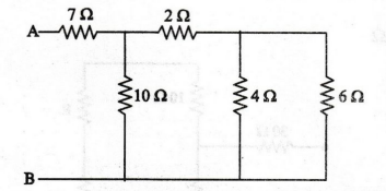
Solution
4
Ω and 6 Ω are connected in parallel.
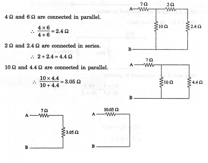
Resistance
across AB = 10.05Ω
EXAMPLE
46:
What is the value of R1, to divide the current as shown in
circuit.
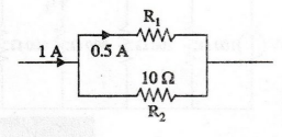
Solution
Current
through 10 Ω resistor is 0.5 A.
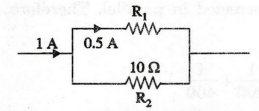
Therefore
the resistance R1 = 10Ω
EXAMPLE
47:
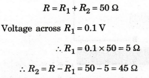
A voltage divider circuit of two resistors is designed with a total
resistance of the two resistors equal to 50 2. If the output voltage is 10% of
the input voltage, obtain the values of the two resistors in the circuit.
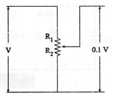
Solution
EXAMPLE
48:
In figure, apply current divider rule to find I3.

Solution
Here,
4 resistors are corrected in parallel. Therefore, the equivalent resistance is
except 300 Ω
EXAMPLE
49:
Apply Ohms law in the circuit given in figure to find V and I2
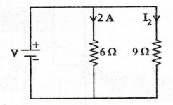
Solution:
Voltage
drop in 6Ω IR = 2 × 6 = 12 V
Supply
voltage V = 12 V
Current
through 9Ω, I2 = V / R2 = 12 / 9 = 1.33 A
I2
= 1.33 A
EXAMPLE
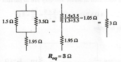
50:
The resistances of 1.5 2 and 3.5 2 are connected in parallel and this
parallel combination is connected in series with a resistance of 1.95 2.
Calculate the equivalent resistance value. (AU, Trichy/EEE - June 2009)
Solution
EXAMPLE
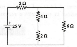
51:
Find the current, I supplied by the source in the following circuit.

Solution
2
Ω and 4 Ω are connected in series
2
+ 4 = 6Ω
6Ω
and 3 Ω are connected in parallel
6
× 3 / 6 + 3 = 2 Ω
4Ω
and 4Ω are connected in parallel
→
4 × 4 / 4 + 4 = 2 Ω
Now,
the circuit becomes
4
Ω and 2Ω are connected in series and they are in parallel with 6 Ω resistor.
4
Ω + 2 Ω = 6Ω
6
× 6 / 6 + 6 = 36 / 12 = 3 Ω
Now,
the circuit becomes

Current
supplied by source I = 25 / 2 + 3 = 25 / 5 = 5A
I
= 5 A
EXAMPLE
52:
Determine the current I delivered by the source.
Solution
3
Ω and 3 Ω are connected in series
3
+ 3 = 6Ω
Now,
the circuit becomes
6
Ω and 6 Ω are connected in parallel
6
× 6 / 6 + 6 = 3 Ω
Now,
the circuit becomes
EXAMPLE
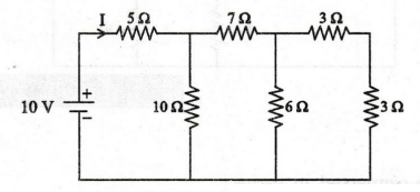
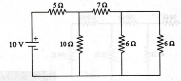
53:
Find the current supplied by 10 V source shown in figure using resistor
reduction.
Solution
220
and 100 Ω are connected in series. i.e 220 + 100 = 320 Ω
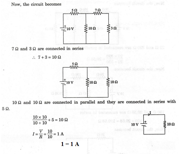
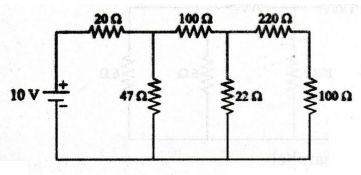
Now,
the circuit becomes
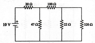
22
and 320 Ω are connected in parallel

100
Ω and 20.58 Ω are connected in series
100
+ 20.58 = 120.58 Ω
Now,
the circuit becomes

47
Ω and 120.58 Ω are connected in parallel
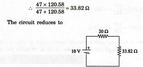
Here,
20 Ω and 33.82 Ω are connected in series
20
+ 33.82 = 53.82 Ω
Current
I = 10 / 53.82 = 0.185 A
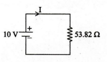
I
= 0.185 A
EXAMPLE
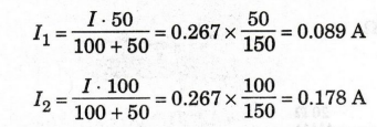
54: Calculate the current through 50 2 and 100 resistors
in the circuit shown below.
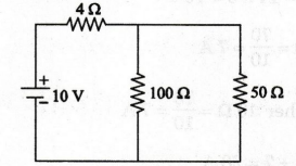
Solution
First
find the total resistance of the circuit
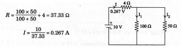
By
using current division rule,
EXAMPLE
55:
A 2 2 resistor is in series with a parallel combination of three resistors
102, 10 2 and 5 2. If the current through the 5 2 resistor is 14 A. What is the
total voltage across the entire circuit? (AU, Trichy/EEE - May 2009)
Solution
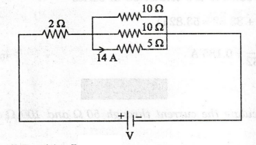
Voltage
across 5 Ω = 14 × 5 = 70 V
Current
through 10 Ω = 70 / 10 = 7 A
Current
through another 10 Ω = 70 / 10 = 7A
Total
current = 14 + 7 + 7 = 28 A
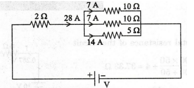
Voltage
across the 2 Ω = 28 × 2 = 56 V
Voltage
across parallel combination = 70 V
Total
voltage V = 56 + 70 = 126 V
V
= 126 V
Electric Circuit Analysis: Chapter - 1: Basic Circuit Analysis - DC : Tag: : with Example Problems - Difference between series and parallel circuits