Digital Logic Circuits: Solved Paper
DLC Solved Semester Question Paper 2016 May (2013 Reg)
Digital Logic Circuits
Digital Logic Circuits: Solved Paper : Sem – III [EEE] : PART A, B, C
Solved Paper
Sem – III [EEE] Regulation 2013
MAY - 2016
Digital Logic Circuits
Time
: 3 Hours] [Total Marks : 100
PART
A - (10 × 2 = 20 Marks)
Q.1
Construct OR gate and AND gate using NAND gates. (Refer section 3.9.2.1)
Q.2
Convert the following Excess - 3 numbers into decimal numbers,
a)
1011 b) 1001 0011 0111
Ans.
:
a)
(1011)Excess - 3 = (1000)BCD = 8 DECIMAL
b)
(1001 0011 0111)Excess - 3 = (0110 0000 0100)BCD = (604)Decimal
Q.3
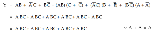
Convert the given expression in canonical SOP form Y = AB + A'C + BC'.
Ans.
:
Q.4
Draw the truth table of 2 : 1 MUX. (Refer section 3.17.1)
Q.5
Differentiate Mealy and Moore model. (Refer section 5.2.3)
Q.6
Draw the state diagram of JK flip flop. (Refer section 4.8.2)
Q.7
What is static hazard and dynamic hazard? (Refer Q.3 and Q.5 of Chapter - 8)
Q.8
Define races in asynchronous sequential circuits. (Refer Q.13 of Chapter - 7)
Q.9
Write VHDL behavioral model for D flip flop. (Refer section 10.14.1)
Q.10
Write the VHDL code for a logical gate which gives high output only when both
the inputs are high.
Ans.
:
A logic gate which gives high output only when both the inputs are high is AND
gate.
VHDL
Description of AND gate
entity
AND_G is
port
(A, B : in bit;
Y
: out bit);
end
ANDG;
architecture
ANDGate of AND_G is
begin
Y
< = A and B;
end
AND_Gate ;
PART
B - (5 × 13 = 65 Marks)
Q.11
a) i) Explain with an aid of circuit diagram the operation of 2 input CMOS NAND
gate and list out its advantages over other logic families.
(Refer
sections 2.6.4 and 2.6.7) [10]
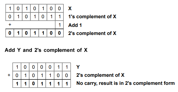
ii)
Given the two binary numbers X = 1010100 and Y = 1000011, perform the
subtraction Y - X by using 2's complements. [3]
Ans.
:
Find 2's complement of X
OR
b)
i) Explain in detail the usage of Hamming codes for error detection and error
correction with an example considering the data bits as 0101. (Refer section
1.8.3) [10]
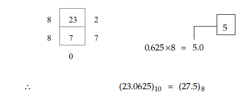
ii)
Convert 23.62510 to octal
(base 8). [3]
Ans.
:
Q.12
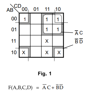
a) Simplify the logical expression using K-map in SOP and POS form F(A, B, C,
D) = ∑ m(0, 2, 3, 6, 7) + d(8, 10, 11, 15) [13]
Ans.
:
Sum of product expression
Product
of sum expression - Refer example 3.5.5.
OR
b)
Design a full subtractor and realise using logic gates. Also, implement the
same using half subtractors.
(Refer
section 3.12.2) [13]
Q.13
a) Design a sequence detector that produces an output '1' wherever the non -
overlapping sequence 101101 is detected.
(Refer
example 5.10.6) [13]
OR
b)
i) Explain the realization of JK flip flop from T flip flop.
(Refer
example 4.9.3) [7]
ii)
Write short notes on SIPO and draw the output waveforms.
(Refer section 6.3.2) [6]
Q.14
a) Design an asynchronous circuit that has two inputs xl and x2 and one output
z. The circuit is required to give an output whenever the input sequence (0,
0), (0, 1) and (1, 1) received but only in that order.
(Refer
example 7.6.10) [13]
OR
b)
i) Design a PLA structure using AND and OR logic for the following functions.
F1
= ∑m (0,1, 2, 3, 4,7,8, 11, 12, 15), F2 = E ∑ (2, 3, 6, 7, 8, 9, 12, 13)
F3
= ∑ m (1,3,7,8,11, 12, 15), F4 = E ∑ (0, 1,
4, 8, 11, 12, 15)
ii)
Compare PLA and PAL circuits. (Refer section 9.5) [3]
Q.15
a) Explain in detail the concept of structural modeling in VHDL with an example
of full adder.
(Refer
section 10.3.3) [13] [10]
OR
b)
i) Write a short notes on built-in operators used in VHDL programming.
(Refer
section 10.6.6)
ii)
Write VHDL coding for 4x1 multiplexer.
(Refer
listing 10.8.2)
PART
C - (1 × 15 = 15 Marks)
16
a) Assume that there is a parking area in a shop whose capacity is 10. No more
than 10 cars are allowed inside the parking area and the gate is closed as soon
as the capacity is reached. There is a gate sensor to detect the entry of car
which is to be synchronized with the block pulse. Design and implement a
suitable counter using JK flip flops. Also, determine the number of flip flops
to be used if the capacity is increased to 50. [15]
OR
b)
Design a 4 bit code converter which converts given binary code into a code in
which the adjacent number differs by only 1 by the preceding number. Develop
VHDL coding for the above mentioned code converter.
(Part
- I - Refer example 3.21.4) [15]
Ans.
:
A code in which adjacent number differs by only 1 by the preceding number is a
gray code. Thus we have to write a VHDL program for binary to Gray code
converter.
LIBRARY
IEEE:
USE
IEEE.ST_LOGIC_1164.ALL;
USE
IEEE.STD_LOGIC_ARITH.ALL;
USE
IEEE.STD_LOGIC_UNSIGNED.ALL;
ENTITY
BINARYGRAY IS
PORT(
B: IN STD_LOGIC_VECTOR(3 DOWNTO 0);
G:
OUT STD_LOGIC_VECTOR(3 DOWNTO 0));
END
BINARY_GRAY;
ARCHITECTURE
BEHAVIORAL OF BINARY_GRAY IS
BEGIN
G(3)<=
B(3);
G(2)<=
B(3) XOR B(2);
G(l)<=
B(2) XOR B(l);
G(0)<=
B(l) XOR B(0);
END
BEHAVIDORAL;
Digital Logic Circuits: Solved Paper : Tag: : Digital Logic Circuits - DLC Solved Semester Question Paper 2016 May (2013 Reg)
Related Topics
Related Subjects

Digital Logic Circuits
EE3302 3rd Semester EEE Dept | 2021 Regulation | 3rd Semester EEE Dept 2021 Regulation